Colors based on wrapped procedural textures
Brick, Paver:
This shader allows the user to choose between several different patterns, to use different colors and parameters. There are set in the Brick, Paver Options dialog shown in Figure 2.2.8.
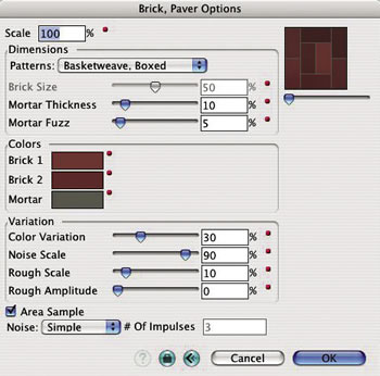
Dimensions: This group of parameters controls the sizes of the pattern, as follows:
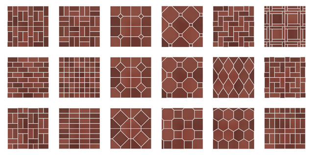
Patterns: A number of patterns can be selected from this pop up menu: Herringbone, Pinwheel, Boxed Basketweave, Double Basketweave, Single Basketweave, Diamonds, Hexagon, Running Bond, Stacked Bond, Combination Running/Stacked Bond, Squares, and Octagon.
Brick Size: This parameter controls the brick layout of certain patterns. It is dimmed when it cannot be applied.
Mortar Thickness: This parameter controls the amount of space between bricks.
Mortar Fuzz: This parameter controls the antialiasing between the edge of a brick and mortar.
Colors: The colors shown in the three boxes are used to generate the paver pattern. They can be redefined in the usual way (double click on them to invoke the color wheel).
Variation: This group of options controls how details of a pattern vary.
Color Variation: This parameter controls the variation in the tone of different bricks.
Noise Scale: This parameter controls the noise pattern that mixes the two brick colors.
Rough Scale: This parameter controls the amount of the variations on the brick edges.
Rough Amplitude: This parameter controls the size range of the variations.
Noise: This pop up menu controls the noise pattern that mixes the two brick colors.
Examples of patterns that can be generated with this shader are shown in Figures 2.2.9 and 2.2.10.
|
|
|
|||
|---|---|---|---|---|
Scale |
300 |
300 |
300 |
300 |
Pattern |
Basket Weave, Box |
Hexagon |
Octagon |
Stacked Bond |
Brick Size |
50 |
50 |
50 |
50 |
Mortar Thickness |
25 |
25 |
25 |
25 |
Mortar Fuzz |
10 |
10 |
10 |
10 |
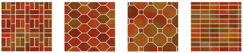
Figure 2.2.9: Brick, Paver textures displayed on 8' x 8' squares
Brick, Simple:
This shader generates a simple brick pattern, in which all bricks have the same color. Its dialog and parameters are shown in Figure 2.2.11.
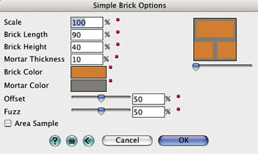
Brick Length, Brick Height: These parameters represent the horizontal and vertical dimensions of a brick, expressed as percentages of the texture tile.
Mortar Thickness: This parameter controls the width of the mortar, expressed as a percentage of the tile. Note that if the tile is not square, the vertical and horizontal mortar lines will have different widths.
Offset: This parameter determines how the vertical mortar joints line up. At 50% they are centered relative to the bricks on the row above them. At 0% or 100% they are aligned with the vertical joints on the row above them.
Fuzz: This parameter controls the smoothness of the edges in the brick pattern. A value of 0% creates crisp edges. 100% fuzz causes blurred edges.
|
|
|
|||
|---|---|---|---|---|
Scale |
100 |
100 |
100 |
100 |
Brick Length |
90 |
90 |
30 |
200 |
Brick Height |
40 |
40 |
60 |
30 |
Mortar Thickness |
10 |
25 |
10 |
10 |
Offset |
50 |
50 |
50 |
50 |
Fuzz |
50 |
50 |
50 |
50 |
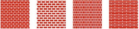
Figure 2.2.12: Simple Brick textures displayed on 4' x 4' squares.
Brick, Textured:
This shader generates a more detailed brick texture. The side of each brick (stretcher) has a base color, randomly assigned from two colors. The bricks are painted with the base color and are textured randomly using the second color variation. The front of each brick (header) is painted with two different colors allowing for varying patterns of stretchers and headers (Figure 2.2.13).
Figure 2.2.13: The Textured Brick Options dialog.
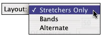
Figure 2.2.14: The Layout pop up menu.
1 |
|||
|---|---|---|---|
a |
b |
c |
|
2 |
|||
a |
b |
c |
|
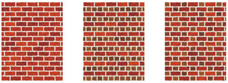
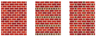
Figure 2.2.15: Textured Brick of Layout type (a) Stretchers Only, (b)
Bands, and (c) Alternate with # Of Stretchers (1) 1 and (2) 3.
Bonds: These options specify a brick pattern.
Layout: Three brick styles can be selected from this pop up menu: Stretchers Only, Bands, and Alternate (Figure 2.2.14).
The Bands and Alternate bond styles generate additional bricks, whose headers are visible. The dimension of the brick ends is determined by the value in the Brick Depth field. The color of the brick headers can be different from the color of their stretchers and is determined by the additional two color fields.
Stretchers Only: This bond style only generates rows of stretchers, that is bricks whose sides are visible (Figure 2.2.15(1a)).
Bands: This style consists of alternating rows of stretchers (bricks whose sides are visible) and rows of bricks whose headers are visible (Figure 2.2.15(1b)).
Alternate: This layout generates rows of bricks that alternate between their stretchers and their headers being visible (Figure 2.2.15(1c)).
Offset: This option sets the horizontal offset between two rows of bricks. At 50%, the vertical joint of one stretcher brick in the Stretchers Only and Bands layout is located in the center of the stretchers above. At 100% or 0%, the vertical joints are aligned. In the Alternate layout, the offset determines the horizontal offset between the header bricks of two different rows.
# Of Stretchers: The number entered in this field determines how many times the stretchers will be repeated. When used with Bands, complete rows are repeated (Figure 2.2.15(2b)). When used with Alternate, it affects the number of stretchers arranged horizontally (Figure 2.2.15(2c)). This parameter has no effect on the Stretchers Only style (Figure 2.2.15(2a)).
Dimensions: This group of options determines the sizes of the bricks and mortar joints through the following parameters: Scale, Length, Height, Depth, and Mortar.
Colors: This group of options consists of color boxes, which can be changed by clicking on them to invoke the standard color picker dialog.
Stretcher 1, Stretcher 2: These colors are used to paint the stretchers of bricks. The first is the base color; the second is used to apply a random texture on the first.
Header 1, Header 2: These colors are used to paint the headers of bricks, whenever they are included in the layout. The first and second colors are used as they are for the stretchers.
Variation: These parameters determine the shape of the edges of the bricks.
Rough Scale, Rough Amplitude: These slider parameters control the size and the depth of the roughness of the edges between the bricks and the mortar.
Fuzz: As for Brick, Simple.
|
|
|
|||
|---|---|---|---|---|
Scale |
200 |
200 |
200 |
200 |
Brick Length |
90 |
90 |
90 |
90 |
Brick Height |
40 |
40 |
40 |
40 |
Mortar |
10 |
10 |
20 |
20 |
Rough Scale |
0 |
50 |
100 |
25 |
Rough Amplitude |
0 |
50 |
25 |
100 |
Fuzz |
50 |
50 |
50 |
50 |
_opt.jpg)
|
|
|
|||
|---|---|---|---|---|
Scale |
200 |
200 |
200 |
200 |
Brick Length |
90 |
90 |
90 |
500 |
Brick Height |
40 |
40 |
40 |
10 |
Mortar |
10 |
10 |
20 |
10 |
Rough Scale |
500 |
50 |
500 |
500 |
Rough Amplitude |
500 |
5000 |
5000 |
5000 |
Fuzz |
50 |
50 |
50 |
50 |
_opt.jpg)
Figure 2.2.16: Textured Brick textures for Stretchers Only layout.
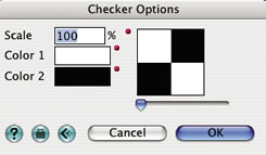
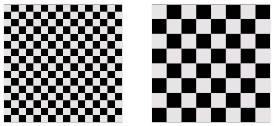
Checker:
This shader generates a checker board pattern from two colors, as shown in its dialog, Figure 2.2.17.
| |
Figure 2.2.18: Wrapped Checker textures |
||||||||
|---|---|---|---|---|---|---|---|---|---|
Fabric:
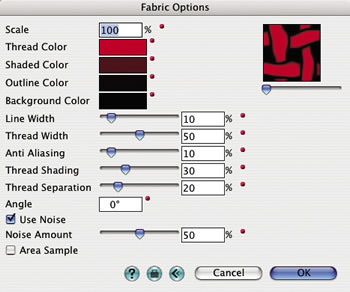
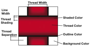
This shader simulates a woven pattern. It can be used to render a wood lattice fence, a wood basket, or cloth. The parameters in the Fabric Options dialog (Figure 2.2.19) control color, dimensions of the threads, and background. They are graphically shown in Figure 2.2.20.
Thread Color: The base color of the threads.
Shaded Color: The color with which the thread is interpolated towards the edges of the threads.
Outline Color: The color of the border lines.
Background Color: The color of any area not covered by thread.
Line Width: The width of the outline along threads. It can be set to 0 if no outline is desired.
Thread Width: The width of thread, not including the outlines.
Anti-Aliasing: This sliding bar controls how much the outline is interpolated into the background and into the thread color.
Thread Shading: This sliding bar controls the distance over which the thread color is interpolated with the shaded thread color. Can be set to 0 if no shading is desired. No shading will give the appearance of a flat object.
Thread Separation: This controls the distance over which the thread color is interpolated with the shaded color, as the one thread goes under another thread.
Angle: The value in this field determines the rotation angle of the fabric.
Use Noise: When this option is on, noise is applied to the thread pattern.
Noise Amount: This sliding bar determines how much noise will be applied.
Examples of the Fabric shader are shown in Figure 2.2.21. Note that this shader and the examples also include Transparency and Bump parts, which are discussed in sections 2.4 and 2.5, respectively.
| Color |
|
||||
|---|---|---|---|---|---|
Scale: |
100% |
150% |
200% |
200% |
100% |
Thread Color: |
r: 255 g: 255 b: 255 |
r: 255 g: 255 b: 255 |
r: 255 g: 255 b: 255 |
r: 243 g: 243 b: 243 |
r: 175 g: 175 b: 175 |
Shaded Color: |
r: 200 g: 200 b: 200 |
r: 200 g: 200 b: 200 |
r: 100 g: 100 b: 100 |
r: 220 g: 220 b: 230 |
r: 125 g: 125 b: 125 |
Outline Color: |
r: 60 g: 60 b: 60 |
r: 40 g: 40 b: 40 |
r: 25 g: 0 b: 0 |
r: 25 g: 0 b: 0 |
r: 0 g: 0 b: 0 |
Background Color: |
r: 0 g: 0 b: 0 |
r: 0 g: 0 b: 0 |
r: 100 g: 100 b: 100 |
r: 0 g: 0 b: 0 |
r: 0 g: 0 b: 0 |
Line Width: |
10 |
1 |
0 |
0 |
5 |
Thread Width: |
50 |
35 |
80 |
45 |
10 |
Anti Aliasing: |
10 |
10 |
5 |
5 |
10 |
Thread Shading: |
50 |
70 |
0 |
0 |
40 |
Thread Separation: |
25 |
35 |
20 |
55 |
10 |
Use Noise: |
ON |
ON |
OFF |
OFF |
OFF |
Noise Amount: |
20 |
50 |
n/a |
n/a |
n/a |
Area Sample: |
ON |
ON |
ON |
ON |
OFF |
|
|
|
|
|
|
Transparency: |
None |
Match Color Shader |
Match Color Shader |
Match Color Shader |
Match Color Shader |
|
|
|
|
|
|
Bump |
None |
|
|
|
None |
Scale: |
|
100% |
100% |
100% |
|
Thread Amp: |
|
45 |
20 |
45 |
|
Shaded Amp: |
|
0 |
0 |
0 |
|
Outline Amp: |
|
0 |
0 |
0 |
|
Background: |
|
0 |
0 |
0 |
|
Line Width: |
|
0 |
0 |
0 |
|
Thread Width: |
|
45 |
80 |
45 |
|
Anti Aliasing: |
|
15 |
5 |
5 |
|
Thread Shading: |
|
45 |
0 |
0 |
|
Thread Separation: |
|
70 |
20 |
55 |
|
Use Noise: |
|
ON |
OFF |
OFF |
|
Noise Amount: |
50 |
n/a |
n/a |
||
Area Sample: |
ON |
ON |
On |
||
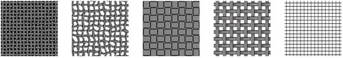
Figure 2.2.21: Examples of Fabric.
Following are some suggestions for achieving better results:
If the direction of the threads follows the shape of the surface, build the surface and map the texture using Parametric as the Mapping Type.
If the material uses a transparent color, set the Background Color to the same color as the edge of the thread. If there is an outline thickness, set the background to the same color of the outline color. If there is no outline, set the background to the same color as the shaded thread. If the threads have no shading, set the background to the same color as the thread. This will prevent the shader from forming a “halo” as the threads fade from opaque to transparent.
Gradient:
This wrapped shader creates a pattern by interpolating between colors. By default, it starts with two colors, but additional colors (up to a maximum of 50) can be added and positioned relative to the others. This shader can be used for color, transparency, reflection, bump, and background. Its parameters can be set in the Gradient Options dialog shown in Figure 2.2.23.

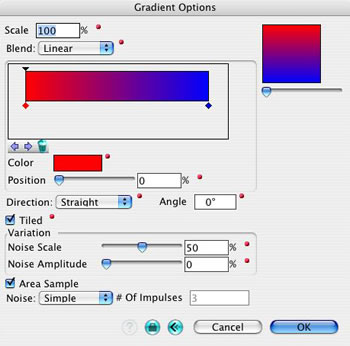
Blend: This pop up menu contains three choices for interpolating colors into each other. They are illustrated in Figure 2.2.22.
None: With this item selected, no interpolation is applied, which causes an abrupt shift from one color to another.
Linear: This item causes a direct interpolation between two colors.
Smooth: With this item, the interpolation curve is flattened near the ends of the line, which causes the ends of the transition to be less noticeable.
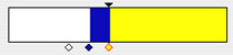
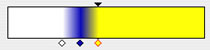
Color Mixer: This is a horizontal rectangle, found under the Blend menu. It can be used to mix colors, to introduce new and delete colors, interactively.
For each color in the rectangle, a little diamond is displayed under it. Above one of the colors, a small triangle is also displayed, while the diamond is highlighted in red, which signifies that the color is active. These handles are used to apply operations, as follows:
-
Clicking on a diamond makes that color active and displays a triangle above it. When active, the attributes of a color can be edited numerically using options in the dialog.
-
-
Clicking inside the rectangle generates a new color, which is initially the color shown at the click point. This color is also displayed in the Color box. Clicking on the box invokes the Color Wheel, which allows you to redefine the color in the usual manner.
-
-
Clicking and dragging a diamond repositions the respective color relative to the other colors. When two diamonds get close to each other, the one on the right will move down, preventing it from obscuring the other. Each additional close marker will be moved farther down.
-
-
The left and right arrow buttons, found under the mixer can be used to move the active color to the next color. The sequence is circular and after the last color the selection moves to the first.
-
-
Clicking on the trash button delete the active color.
Position: The value displayed in this alpha field represents the position of the active color, Changing this value either numerically or by using the slide rule repositions the active color. Or, reversely, when moving the active color the value in the field changes.
a  b
b  c
c  d
d 
Figure 2.2.24: Direction options:(a) Straight and
Angle=0°, (b) Straight and Angle=45°, (c)
Radial, and (d) Circular
Direction: This pop up menu controls the shape of the gradient, as shown in Figure 2.2.24.
Straight: When this item is selected, which is the default, the gradient follows a linear path. The angle of this path is controlled by the Angle option.
Radial: With this item selected, the path of the interpolation runs around a circular path, which causes the colors to radiate from the center of the texture sample.
Circular: With this item on, the gradient interpolates from the center of the sample towards the outside. This option forms concentric rings.
Angle: The value entered in this field determines the orientation of the Straight and Radial gradients.
Variation: This group of options allows one to add randomness to the pattern.
Noise Scale: This slide rule controls the size of the noise pattern.
Noise Amplitude: This slide rule controls the intensity of the noise pattern.
Area Sample, Noise Quality, # Of Impulses: As for the other shaders.
Examples of Gradient textures are shown in Figure 2.2.25.
|
|
|
|||
|---|---|---|---|---|
Scale |
100 |
800 |
100 |
400 |
Blend |
Smooth |
Linear |
Smooth |
Smooth |
Direction |
Straight |
Straight |
Radial |
Circular |
Tiled |
ON |
ON |
ON |
OFF |
Noise Scale |
50 |
50 |
50 |
50 |
Noise Amplitude |
0 |
50 |
0 |
100 |
Noise |
Simple |
Simple |
Best |
Simple |
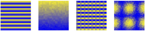
Figure 2.2.25: Gradient textures.
Grid:
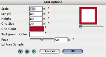
This shader generates a two color grid pattern whose tiles can be square or have different horizontal and vertical dimensions. Its dialog is shown in Figure 2.2.26.
|
|
|
|||
|---|---|---|---|---|
Scale |
100 |
100 |
100 |
100 |
Width |
80 |
80 |
80 |
20 |
Height |
80 |
40 |
400 |
20 |
Grid Size |
20 |
20 |
20 |
30 |
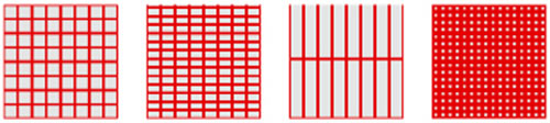
Figure 2.2.27: Grid textures.
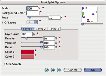
Paint Splat:
a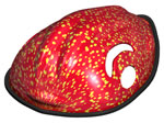 b
b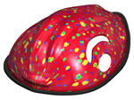 c
c
Figure 2.2.29: The Paint Splat color shader applied to a bike helmet.
(a) One, (b) three, and (c) five layers.
This shader generates a pattern of one or more layers of random dots on a plain background color. Each layer has its own parameters that allow the user to change the color, size and shape of the dots.
Background Color: The plain background color on which the dot layers are placed.
Fuzz: This parameter controls the smoothness of the edge between the dots and the background.
# Of Layers: From this menu the number of dot layers is chosen. From 1 to 5 layers are supported. The dots of Layer 1 are always rendered first, with the other layers placed on top. The parameters of each layer are shown in a separate tab.
Layer Scale: This parameter applies an additional scale to the dots. This allows the user to create layered dots of different sizes.
Density: When this parameter is increased, more dots will cover the background. A low density parameter will generate less dots.
Variation: When this parameter is set to 0%, all dots have the same size. At 100%, the dots will vary randomly from a small size up to the size they would be at 0%.
Detail: At 0% the dots will be perfectly circular. Increasing the detail parameter will result in a rougher dot edge.
Color 1, Color 2: The color of the dots is a random mixture of these two colors.
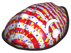
The Paint Splat shader may also be used very effectively as a decal. In the example below, the bike helmet is assigned the Stripe color shader as its main material. A decal material is created with the Paint Splat shader for the color shader and also for the transparency shader. As a transparency shader, the paint splat pattern acts as a stencil, rendering just the dots, but not the background. With the Decal tool, the paint splat decal material is assigned as a decal to the helmet surface. The resulting rendering is shown in the Figure 2.2.30.
Polka Dots:
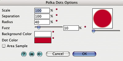
This shader generates a flat dot pattern based on values entered for the size of and distance between the dots, as well as the smoothness of their edges. Its dialog is shown in Figure 2.2.31.
Separation: This parameter, expressed as a percentage of the tile size, represents the distance between the centers of the dots.
Radius: This parameter represents the radius of the polka dots relative to the tile size.
Fuzz: This slider parameter controls the smoothness of the edge between the dots and the background color.
Note that radius values greater than 50 (with separation at 100%) result in overlapping dots. Separation values other than 100% result in scaled tiles.
|
|
|
|||
|---|---|---|---|---|
Scale |
100 |
100 |
100 |
100 |
Separation |
100 |
100 |
200 |
100 |
Radius |
40 |
20 |
20 |
55 |
Fuzz |
10 |
10 |
120 |
10 |
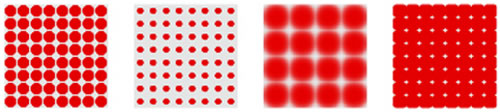
Figure 2.2.32: Wrapped Polka Dots.
Roof Tiles:
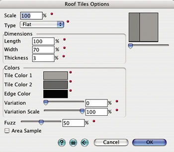
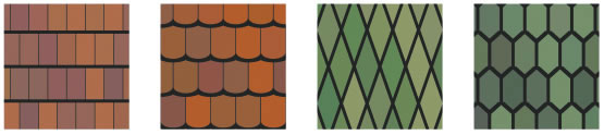
This shader generates a pattern of roof shingles or roof tiles. The Type menu offers eight different styles: Flat, Scalloped, Diamond, Hexagonal, Classic, Espana, Spanish, and Roma. Examples of all eight patterns are shown in Figure 2.2.34.
The dimensions and colors of the tiles are entered in the Dimensions and Colors option groups. The Variation slider determines how much color variation occurs on each tile. The variation is displayed as a pattern of light and dark patches. The Variation Scale slider determines the size of the patches. The Roof Tiles Options dialog is shown in Figure 2.2.33.
| |
|||
|---|---|---|---|
a |
b |
c |
d |
| |
|||
|---|---|---|---|
e |
f |
g |
h |
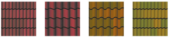
Figure 2.2.34: The 8 Roof Tiles patterns (a) Flat, (b) Scalloped, (c) Diamond, (d) Hexagonal,
(e) Classic, (f) Espana, (g) Spanish, and (h) Roma.
Sine Wave:
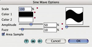
This shader generates a sine wave pattern of two colors. Its dialog is shown in Figure 2.2.35.
Amplitude: Height the sine wave reaches.
Fuzz: How much the colors along the edges of the sine wave blur together.
|
|
|
|||
|---|---|---|---|---|
Scale |
100 |
150 |
100 |
250 |
Amplitude |
50 |
20 |
100 |
100 |
Fuzz |
10 |
10 |
100 |
50 |

Figure 2.2.36: Sine Waves textures.
Stripes:
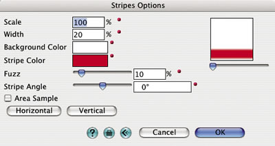
This shader generates two color striped patterns of variable width and orientation, using the parameters shown in Figure 2.2.37.
Width: This parameter represents the width of the stripe, expressed as a percentage of the tile size. Note that, contrary to other shaders, values greater than 100 entered for this parameter do not scale the texture tile, but the width of the stripe is always trimmed by the edge of the tile.
Fuzz: This parameter controls the smoothness of the edges between the stripes. Note that if Width is set to 100 or greater and Fuzz is set to 0, no stripes will appear.
Stripe Angle: This slider parameter determines the direction of the stripes. The default value is 0°, which corresponds to a position of the knob in the middle of the slider bar and generates horizontal stripes. Positions of the knob to the left of the middle correspond to negative angles, and positions to the right correspond to positive angles. The maximum angle possible is 90° (vertical stripes). Values greater than 90 that are entered into the text field are adjusted by an increment of 90°.
Horizontal, Vertical: These buttons can be used to directly set the stripes’ angle to 0° (horizontal) or 90° (vertical) orientations.
|
|
|
|||
|---|---|---|---|---|
Scale |
100 |
100 |
100 |
40 |
Width |
20 |
20 |
20 |
50 |
Fuzz |
0 |
100 |
10 |
10 |
Stripe Angle |
0 |
90 |
45 |
-45 |
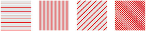
Figure 2.2.38: Stripes textures.
Wood Boards:
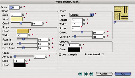
This shader offers advanced parameters to simulate the irregular patterns generated by cut wood. It creates board patterns in different layouts, which are filled with wood surfaces. In the Wood Boards Options dialog (Figure 2.2.39), the parameters of the shader are in five groups: Wood, Rings, Grain, Boards, and Grooves.
Wood: These options set the size, color, and irregularity of the concentric wood rings (Gnarl).
Rings: These options set the color, size, and shape of the rings.
Grain: These parameters specify the shape of small dots that produce a grainy appearance.
Boards: These parameters determine the size and shape of the wood boards.
Layout: The item chosen from this menu determines the layout of the wood boards. The available options are Square, Herring Bone, Floor Boards, and Ladder. They are illustrated in Figure 2.2.40.
Length, Width: Sets the length and width of a wood board relative to the overall pattern.
Strips, Offset: Sets the number of repeated boards and their alignment, respectively.
Variation: Sets the amount of color variation between individual boards.
Grooves: These parameters determine the size and color of the grooves between the boards.
Preset Wood: Preset parameters for a number of wood types are chosen from this menu.
| |
|
|
|
|---|
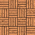
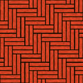
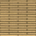
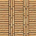
Figure 2.2.40: Examples of the Wood Boards shader with different board layouts:
(a) Square, (b) Herring Bone, (c) Floor Boards, and (d) Ladder.