Setting The Environment
Objects in a scene can be rendered with reflections, which originate from other objects in the scene or from an environment. This environment is assumed to be surrounding the scene, but is not rendered as part of the scene, unless the Environment shader is selected in the Background pop up menu as discussed earlier. Recall that reflections are rendered when the Reflections option is selected from the Shading tab.
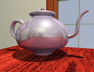
Figure 1.8.7: A teapot rendered with raytraced
reflections and Environment off.
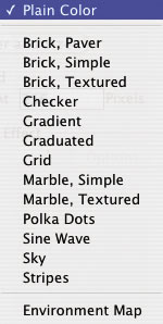
Figure 1.8.8:
The Shader menu.
In the Environment group of options, two distinctly different environments can be defined: mapped and rendered. A mapped environment uses one or six textures, depending on whether the mapping type is spherical or cubic. The pattern of these textures is shown in reflective surfaces. The rendered environment is used in combination with the Environment reflection shader of a material. Instead of using precaptured textures, the reflective pattern consists of six rendered images of the scene, one for each of the orthogonal directions. This is described in more detail later in this section.
Environment: When this option is off, faces to which a reflective shader has been assigned produce reflections from other objects but not from an environment. This is illustrated in Figure 1.8.7. The scene consists of a teapot in a room. Note that the room and its walls are the objects in the scene. The Mirror reflection shader (see section 2.3) has been assigned to the pot and Environment is off. The image shown has resulted from “pure” raytraced reflections causing the room to be reflected on the surface of the pot. The reflections are accurate but require additional time to calculate. Later in this section the same scene is shown rendered using different types of environment reflections. When Environment is on, the two environments, mapped and rendered, can be set up.
The group labeled Type contains the parameters for the mapped environment. It contains two pop up menus and a button. One menu controls the mapping type and the other the selection of a shader.
Shader: This pop up menu, shown in Figure 1.8.8, allows you to select the particular environment shader. This can be of a plain color, procedural, or image based. The dialog containing the settings of the currently selected shader can be invoked by clicking on the Options... button next to the menu. Note that this pop up menu is a subset of the Background menu and the parameters of its shaders are set as for the background.

Figure 1.8.9: The Type
pop up menu.
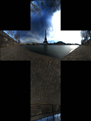
Figure 1.8.10: A cubic cross map.
Type: This pop up menu, shown in Figure 1.8.9, allows you to specify how the environment shader will be mapped. It has two items, as follows:
Cubic: When this item is selected, the shader picked for the environment is mapped onto an imaginary cube from which it is reflected on the surfaces to which reflective shaders have been assigned. If a procedural shader is selected, the respective pattern will be automatically placed on each of the surfaces of the environment cube. If Environment Map is selected, then either a single map or six individual maps are selected to define the image for each side of an imaginary cube surrounding the scene. When choosing six individual maps, a different image map can be used for each side of the cube, or the same map can be repeated for all sides. When choosing a single map, the image map needs to contain all the images for the six sides of the cube in a specific layout, which resembles a cross. Therefore these maps are also referred to as cubic cross maps. An example of such a map is shown in Figure 1.8.10. Note that, unlike the horizontal layout of the six individual images of the environment cube, the cubic cross map presents the sub images in a vertical format. Defining the images and choosing between the two different map types can be done in the Environment Maps dialog (shown in Figure 1.8.11), which is invoked by clicking on the Options... button next to the Environment Map item that is displayed in the Shader pop up menu.
The Environment Maps dialog has two options at the top.
Six Individual Maps: When this option is selected, the dialog displays six squares, each corresponding to a side of the unfolded imaginary cube that surrounds the scene. Initially, the system default texture map is assigned to each side of the cube (Figure 1.8.11(a)).
A new image file can be loaded in each of the squares, as shown in Figure 1.8.11(b). To work properly, these images should be correlated to present a panoramic view of an environment extending around the scene to be rendered. When using a z-buffer or raytrace rendering type, all reflective surfaces will show the portion of the environment toward which they are oriented. Usually, the environment cube itself is not rendered, but only appears in the reflections of the surfaces. However, if the Environment background shader is selected from the Background menu, the portion of the environment which is visible in the current view is rendered as the background. This is discussed in more detail earlier in this subsection.
|
|
|
|---|
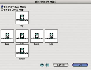
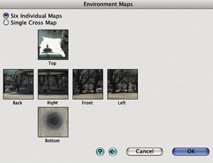
Figure 1.8.11: The Environment Maps dialog with (a) default images and (b) an urban landscape.
Images are loaded into the squares of the environment cube by clicking inside each square. This invokes the Cubic Environment Map Options dialog, shown in Figure 1.8.12. The general options for this type of dialog were discussed earlier. This particular dialog has an additional parameter and an additional button:
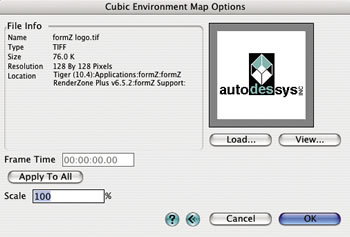
Figure 1.8.12: The Cubic Environment Map Options dialog.
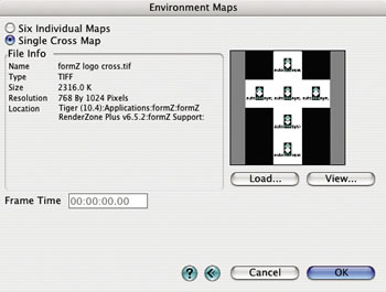
Figure 1.8.13: The Environment Maps dialog with the
Single Cross Map option selected.
- Scale: The value entered in this field determines the size of the image as a percentage of the face of the environment cube. At 100% the whole image will fit exactly from one end of the face to the other. At 25% the image will be repeated four times. Percentages greater than 100% result in partial images being mapped onto the faces of the environment cube.
- Apply To All: Closing the Cubic Environment Map Options dialog by pressing the OK button places the image in the currently edited square of the environment cube, and each of the squares needs to be assigned individually to load other images onto them. Clicking on this button will apply the currently loaded image and all of its parameters to all six sides of the environment cube.
Single Cross Map: When this option is selected, the Environment Maps dialog shows a single cross map (Figure 1.8.13). Initially, this is also a system default texture map, which looks different from the one used for the six individual images. It is properly formatted as a cubic cross map. A new map can be selected in the usual fashion. Note, it is important that the map selected follows the layout convention for the cubic cross map. That is, the six sub images must be ordered in the vertical format, with the top image at the middle top of the map and the remaining sub images unfolding below. Therefore, the width to height pixel ratio of such a map must always be 3 : 4. For example, it may be 768 to 1024 pixels. If an image map with a ratio other than 3 : 4 is selected, an error will be posted when the dialog is closed. Many of the cubic environments distributed as maps are now available as cross maps. While there is some waste of space in the texture map itself, it is more convenient to define the environment cube through a single image map rather than selecting and properly placing six maps. An example of a cubic cross map is shown in Figure 1.8.10.
Spherical: When this item is selected, faces to which a reflective material has been assigned will reflect the pattern generated by an environment shader mapped onto an imaginary sphere that surrounds the modeling scene. That is, this environment is similar to Cubic, except that it applies a spherical rather than a cubic reflection. With this environment, the pattern is wrapped around an imaginary sphere in a way such that the horizontal direction of the pattern runs parallel to the equator of the sphere. The axis of the sphere is always parallel to the world Z axis.
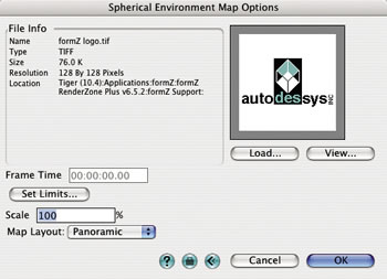
Figure 1.8.14: The Spherical Environment Map Options dialog.
A particular environment shader can be selected from the Environment type pop up menu, as for Cubic. When the Environment Map item is selected, a precaptured image can be mapped onto the environment sphere through the Spherical Environment Map Options dialog shown in Figure 1.8.14. It is invoked by clicking on the Options... button next to the Environment Map item shown in the menu.
The content of the Spherical Environment Map Options dialog is the same as that of the Cubic Environment Map Options dialog, except that the Apply To All option is not available (since only one image is selected and mapped onto the environment sphere), and it has an additional button and menu.
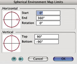
Figure 1.8.15: The Spherical Environment
Map Limits dialog.
Set Limits...: Clicking on this button invokes the Spherical Environment Map Limits dialog shown in Figure 6.1.8.15. It contains options for determining which portion of the environment sphere is covered by the environment map. The default values in this dialog result in a completely curved environment sphere, as shown in Figure 1.8.16.
Horizontal: The options in this box control how the environment image is positioned horizontally.
- Start/End: These angles indicate where the horizontal extents of the image start and end. Defaults are 0 and 360 degrees respectively.
- Rotation: This value indicates the rotation of the environment sphere around the world Z axis. A value of 0 degrees, which is the default, places the start angle of 0 at the world X axis.
Vertical: The options in this box control how the environment map is placed vertically.
Top/Bottom: These angles indicate where the vertical extents of the image start and end.
Alternatively to typing the angles in the text edit fields, the red circles on the left of the dialog allow for graphic editing of the limits. Clicking in one of the handles the angle can be dragged graphically to its desired position. Holding the shift key down while dragging will adjust the horizontal start and end angle or the vertical top and bottom angle symmetrically. Holding the option (Macintosh) or alt (Windows) key allows you to adjust one of the handles at a time without affecting the others.
If a portion of the environment sphere is rendered which is not covered by the image, the colors at the edge of the image are stretched to continue beyond the image limits.
a 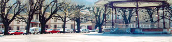
b 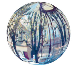
Figure 1.8.16: (a) A panoramic environment image,
(b) wrapped around the environment sphere.
Map Layout: One of two available spherical map functions is selected from this pop up menu:
- Panoramic: When this item is selected, the environment map represents an unfolded and flattened sphere, not unlike a map of the world. Ideally, the proportions of such a map should be 2:1, with the width dimension representing the distance along the equator of the environment sphere and the height representing the distance between the two poles. Once mapped, the area of the image which is along the horizontal middle section will appear least distorted, whereas the area at the top and bottom of the image will be distorted most, since this area will be compressed at the poles. An example of a panoramic environment map is shown in Figure 1.8.16.
- Spherical: When this item is selected, the environment map should show an image that resembles a photograph of a mirror ball that is placed in the middle of a scene. The image reflected in the ball should show the environment to be used in the rendering. An example of such an image is shown in Figure 1.8.17. Environment maps are now commonly distributed in such a format. Note that the area in the map outside of the mirror ball may be black and is not used in the rendering. The width to height ratio of the angular map must be 1:1. If a map of a different proportion is chosen, an error will be posted when the dialog is closed.

Figure 1.8.17: An Spherical environment map, courtesy of Sachform Technology GbR (www.sachform.de)
from the LightWorks HDRI Starter Collection (www.lightworkdesign.com).
Spherical and cubic environment reflections generate slightly different patterns of reflective surfaces. Which one is preferable depends on the particular reflective effect desired and the type of the environment. For example, to generate the interior reflections of a square room one could produce a single image which contains a panoramic view of the entire space. This image can then be mapped onto an environment sphere. With such a mapping, the reflections of the areas that are close to the poles of the sphere will display significant distortions. An alternative and possibly preferable approach in this case would be to capture six images of the room, one for each of the four walls, one looking straight up at the ceiling, and one looking straight down at the floor. The resulting images would then be placed on the respective sides of an environment cube. Reflections from such a cubic environment will show less distortions. On the other hand, if an open environment such as a landscape or sky needs to be reflected, then a spherical environment may produce more appropriate results. Regarding memory requirements, spherical environments are more efficient than cubic environments since the latter requires six images to be stored, versus the one stored for spherical environments.
a 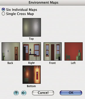
b 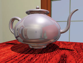
Figure 1.8.18: (a) Images wrapped on the environment
cube, and (b) the teapot rendered using Cubic
environment reflections.
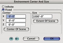
Figure 1.8.20: The Environment
Center And Size dialog.
Examples of environment reflection using cubic and spherical environments are shown in Figures 1.8.18, and 1.8.19, respectively. Note that this is the same scene that earlier (Figure 1.8.11) was shown rendered with no environment, but raytraced reflections.
For the cubic environment, six images of the room are rendered first and then mapped onto the environment cube as shown in Figure 1.8.18 (a). A material that includes the Environment shader with the Mapped item selected from the Global pop up menu (Reflection pop up menu in the Material Parameters palette) is assigned to the teapot. Cubic is selected from the Environment Type pop up menu in the RenderZone Options dialog. When the image is rendered, the reflections from the cubic environment appear as in Figure 1.8.18 (b).
For the spherical environment, the panoramic view of the room shown in Figure 1.8.19(a) is rendered and mapped onto the environment sphere. The Environment shader is assigned to the teapot as before, and Spherical is selected from the Environment Type menu. The resulting image with environment reflections is shown in Figure 1.8.19(b). Observe the similarities and differences between the cubic and spherical reflections.
a 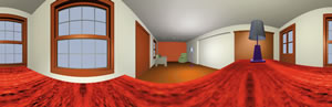
b 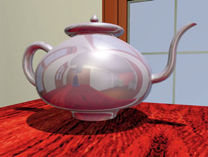
Figure 1.8.19: (a) A panoramic view of the room and (b) the
teapot rendered using Spherical environment reflections.
Center And Size: When this button is selected, the Environment Center And Size dialog is invoked, as shown in Figure 1.8.20. It contains two major options:
Infinite: When this option is selected, the environment cube or sphere is considered infinitely large. The reflection pattern on a surface is calculated from the direction of a ray as it bounces off a surface. As a side effect of this approach, flat surfaces will show little or no variation in the reflected environment, since all the rays reflected off such a surface are exactly parallel in an axonometric view or nearly parallel in a perspective view. Parallel rays will always yield the same color for a pixel in an infinite environment.
Fixed: When this option is selected, the environment has a fixed size and is centered around a given point, which can be entered in the Center and Size fields. For rays reflected off a surface, the true intersection point with a cube or sphere of the given size and location is calculated. The color value of the pattern at that intersection point is used. Parallel rays reflected off a flat surface will now intersect the environment at different points, showing more of the pattern. The smaller the Fixed Size, the larger the reflected pattern will be. Care should be taken that the rendered scene fits inside the extent of the fixed size environment. Surfaces which fall outside of the environment will not show correct reflections. Pressing the Extent of Scene button automatically sets the size field, so that the scene fits entirely inside the environment.
Rendered: The option in this group affects reflections on those objects in the scene that have been assigned the Environment reflection shader that uses the Global Rendered option. The reflections come from objects in the scene to which the Environment shader has not been assigned. Surfaces to which the Environment shader has been assigned do not reflect each other. While the reflective shaders, such as Mirror, produce accurate reflections, they also require additional computing time. In contrast the Environment shader produces simulated reflections and is generally faster. This is described in more detail in subsection 2.3.
When an Environment reflection shader with the Global Rendered option has been included in the materials assigned to one or more objects in a scene, reflections are simulated through the use of an environment cube. Using as view point the center (average coordinates) of all the surfaces to which the Environment reflection shader has been assigned, views of the other objects (those that are not assigned the Environment reflection shader) are generated looking into the direction of each of the squares of the environment cube. These directions are the X, Y, and Z axes of the world space, and views are taken in both their positive and negative directions. These images are then mapped onto the squares of the environment cube, the same way in which precaptured images are mapped when the Cubic mapped environment is used. From this point on, the reflections are calculated from the environment cube as for Cubic.
The resolution of the rendered images is controlled by the Render At n Pixels parameter. The value n entered in its numeric field determines the size at which the images of the objects to be reflected will be rendered.
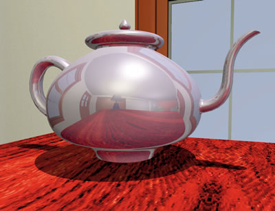
Figure 1.8.21: The teapot rendered using Rendered environment reflections.
An example of an image using rendered environment reflection is shown in Figure 1.8.21. The material assigned to the teapot uses the Environment reflection shader with the Global Rendered option. The material assigned to the room does not. Six rendered images of the room are created and attached to the environment cube. The image is then rendered as with the Cubic environment.
Which portion of an environment is reflected depends on the direction of a reflected ray. This is why reflections generated from spherical, cubic, or rendered environments work best on curved surfaces. For example, a spherical object will reflect a large portion of the environment, since rays bouncing off its surface will point in almost all directions. A cube on the other hand will reflect only a very small portion of the environment, since all reflected rays off each of the sides of the cube are pointing in the same direction, resulting in the same pixel of the environment being assigned to the surface.