Layout and Interface
The form•Z interface is composed of form•Z project windows supported by a set of menus, tool bars, docks and palettes. The project window is the focus of the interface. This is where a 3D model is created, edited, and displayed.
By default the window shows a perspective view into the modeling space. The Cartesian axes are shown to indicate orientation and a grid is displayed to indicate the reference plane and scale. The appearance of the project window, the working units, scale, and other parameters are set in the Project Settings dialog, invoked from the File menu.
The tools used to perform modeling operations are located in the Modeling tool palette to the left of the project window. Each row in the modeling tool palette contains a suite of functionally related tools, whose label appears vertically to the left of the icon. When the cursor is positioned over the icon, the complete tool suite pops-up to the right of the icon. Clicking on an icon in the tool suite makes it the active tool and its icon is displayed in the modeling tool palette. The tool suite can be torn-off by clicking and dragging in its title bar.
There is always one active tool. The active tool is indicated by a red outline around the tool’s icon. Clicking on a tool makes it the active tool. The icon and name of the active tool are shown in the Action palette located at the top of the screen. Most tools have a variety of options that control the functionality of the tool. These options are found in the Tool Options palette located to the right of the project window.
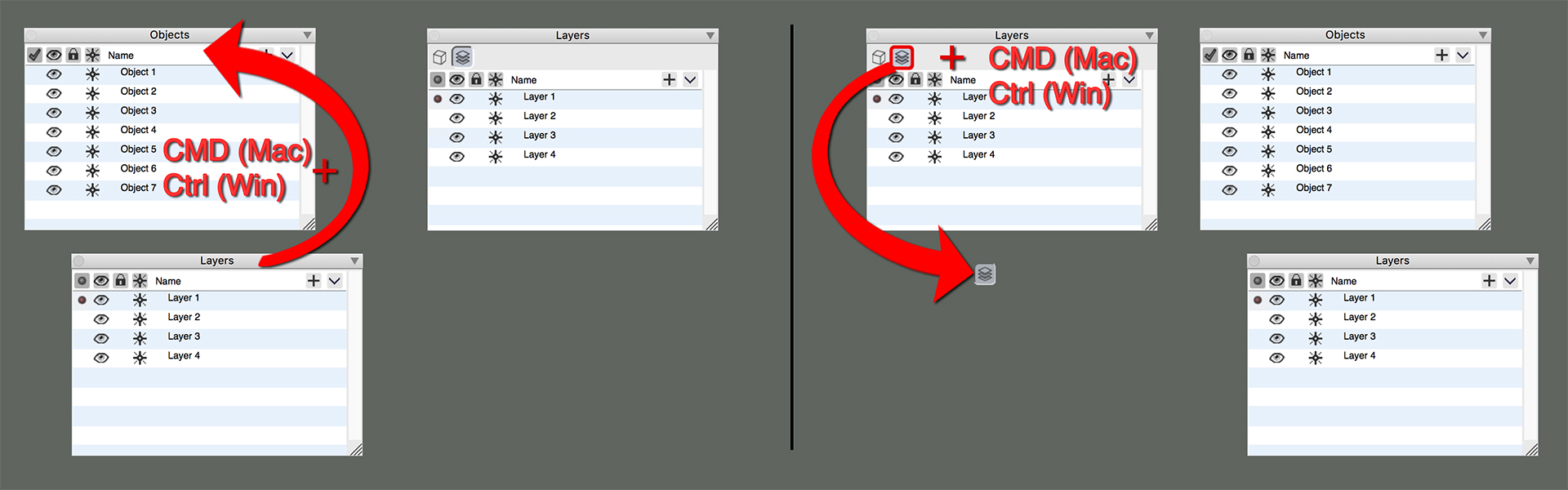
Palettes can be removed from their dock to become floating palettes by Command + click-drag (Mac OS) or Ctrl + click-drag (windows). Palettes can also be removed by right clicking in the palette and selecting Detach from the context menu.
All of the palettes that display project contents (materials, objects, layers, line weights etc.) are now “combo” palettes. The palettes can be combined to save screen space. When combined a row of icons will be displayed at the top the palette for each of the combined content. Selecting the icon displays the respective content in the palette. By default, the Views, Scenes, Reference Planes. Clipping planes, Selection sets, Line weight and Line Styles are combined into a single palette at the bottom of the right dock.
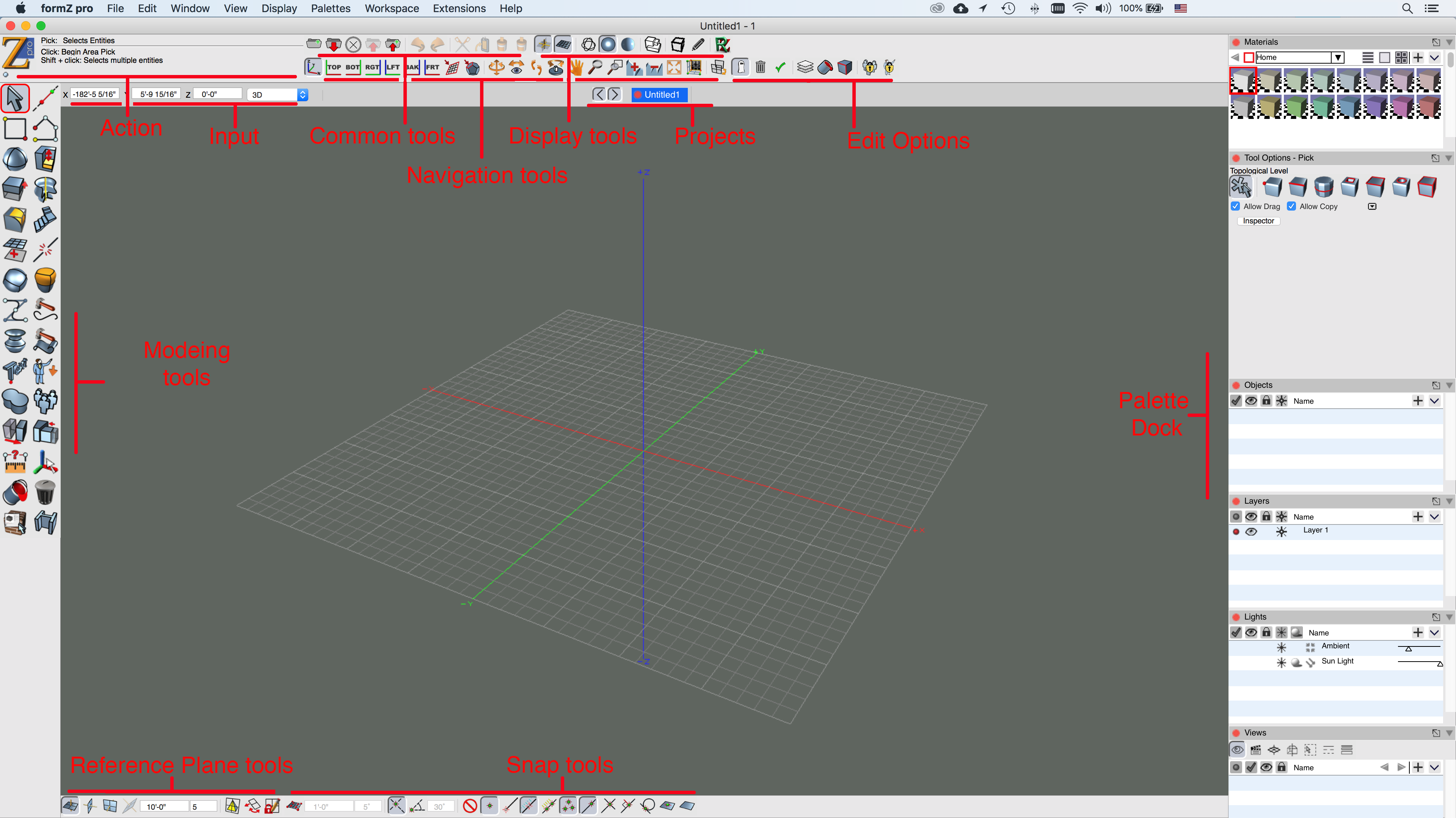
The form•Z Pro screen layout.
All of the palettes that display project contents (materials, objects, layers, line weights etc.) are now “combo” palettes. The palettes can be combined to save screen space. When combined a row of icons will be displayed at the top the palette for each of the combined content. Selecting the icon displays the respective content in the palette. By default, the Views, Scenes, Reference Planes. Clipping planes, Selection sets, Line weight and Line Styles are combined into a single palette at the bottom of the right dock.
Command + click-drag (Mac OS) or Ctrl + click-drag (windows) one palette onto another to combine them. The same method can be used on the icon at the top to drag the content to another palette or into free space to make it independent, re-order the icons, or drag a palette back into the icon toolbar.
If the palette stack on the right exceeds the screen size, use the mouse scroll wheel or option + click-drag (Mac OS) or Alt + click-drag (Windows) to scroll.
The detach icon the palette title bar removes it from the dock. The Dock’s can be rearranged by moving them to the opposite side of the screen. In the context menu for a palette you can select options to move a panel Left/Right or Up/Down. For example, you can move the tool dock to the right of the modeling area.
The active tool determines the action that is applied when clicking in the project window. The basic form•Z workflow is as follows:
Select the desired tool.
Choose the desired options from the tool options palette.
Click in the modeling window as needed to perform the action. The Action palette indicates what each click will do. The Input palette can be used to enter values numerically for many tools.
Review the results. Most tools have the ability to make changes to the result without having to re-execute the tool. These tools show their results in orange in the project window. Tool options can be changed and are immediately reflected in the result object. Some tools provide graphic editing of the result through on screen controls.
Continue to the next operation.
The remaining tool palettes offer additional functionality used to support the modeling functionality. At the bottom of the screen are the reference plane tool and snap tool palettes. At the top of the screen are the display tool and navigation tool palettes. These tool palettes are discussed in more detail later in this document.
The common tools palette is a collection of commonly used items from the File and Edit menus. This includes New Project, Open, Close, Save, Save As, Undo, Redo, Cut, Copy, and Paste.
The properties of a selection are shown in the Inspector Palette. the Selection, Info, Attributes, and Parameters tabs have been moved to the new Inspector palette, making them available at any time for the user! You can access the Inspector window from the Palettes menu, just like any other palette. For convenience an ‘Inspector’ button in the Tool Options palette will open the inspector as well.
![]()
The Edit Options palette allows easy access to some of the commonly used items from the Edit Pull down menu
![]()
Project Navigator Palette is found in the top dock and is a quick way to jump between windows without having to use the Window drop-down list of open projects and windows.
The Materials, Objects, Layers, Lights, Views, Scenes, Custom Reference Planes, and Clipping Planes palettes are all used to manage information of a project.
The Display Options, Material Parameters, Reference Plane Parameters, View Parameters, and Components palettes control the options for the current display, active material, reference plane, view, and components, respectively. These palettes are closed by default but can be opened by selecting the palette’s name from the Palettes menu.
The palettes on the right of the screen reside inside a palette dock. A dock is essentially a palette that holds other palettes. When the dock is moved, all of the palettes in the dock move with it. When a dock is closed, all the palettes in the dock are no longer visible. A palette can be moved out of the dock and positioned anywhere on the screen. The dock on its right side has a scroll bar to allow scrolling of the palettes when the area required by the palettes is larger than the screen.