HPGL
An HPGL (Hewlett Packard Graphics Language v2) file contains commands which control pen plotters (mostly HP plotters, although several other plotter manufactures have also adopted this language). The commands in an HP-GL/2 file represent 2D graphics information in the form of stick text and vector graphics. Vector shapes may be lines, arcs, or Bezier curves. Connected paths can be constructed using those basic shapes. Paths can be drawn with different colors, line styles, and line widths. Paths may be filled with a solid color or a predefined pattern. Typically the purpose of an HP-GL/2 file is to be sent to a pen plotter to be plotted/printed on paper. HP laser printers which support HP’s PCL5 (Printer Control Language v5) can also print HP-GL/2 by setting their print mode to HP-GL. There are also several HPGL software viewers available.
Exporting HPGL files
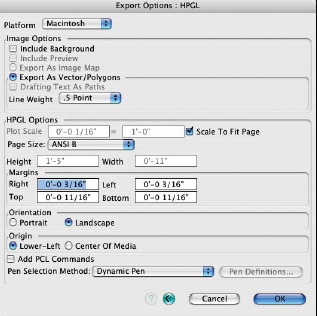
The HPGL export options.
The content of a form•Z window is exported as HP-GL/2 by executing the Export Image command (File menu), in the standard manner. The Export Options: HPGL dialog is shown at right. It contains a number of format specific options. Saving an Hp-GL/2 file exports the content of the active window. When a modeling window is active, the 2D image which is currently displayed on the screen is exported, rather than the 3D representation of the modeling objects.
Since HP-GL/2 does not support pixel images, Shaded Render*, RenderZone*, and Sketch Render* renderings can not be exported. Text objects are exported as outlines since HP-GL/2 does not support fonts.
When a modeling scene is exported, the line thickness is determined by the active Line Weight option on the pull down menu of the Export Options: HPGL dialog. All lines are exported as solid lines. When a drafting window is active, vector line data is exported for the drafting elements currently displayed on the screen. The line weights, line styles, and hatch patterns are exported to match the attributes of the respective drafting elements.
HPGL Options: These are the options specific to the HPGL format, as follows:
Plot Scale: Sets the scale of the drawing on the printed page.
Scale To Fit Page: When this option is selected the drawing scale is automatically set to fit the drawing on a single sheet of paper defined by the Page Size options.
Page Size: This menu contains several standard drawing sizes. The Custom item allows you to define your own page size.
Height, Width: The height and width of the page.
Margins: These values determine the space between the plot area and the edge of the page.
Right, Left, Top, Bottom: The spaces between the right, left, top, and bottom edges of the page and the plot area.
Orientation: Specifies the orientation of the printed page.
Portrait: With this option on, the page is plotted as defined.
Landscape: This option swaps the width and height of the image to be plotted; in other words, it plots the image sideways.
Origin: This value specifies where the origin of the drawing (plotter coordinate 0, 0) is.
Lower-Left: This option places the plotter origin in the lower-left corner of the page.
Center Of Media: This option places the plotter origin in the center of the page.
Add PCL Commands: When this option is selected, PCL5 commands are added to the beginning and end of the HP-GL/2 file. The exported file can then be sent to an HP laser printer. The PCL5 commands set the printer’s mode to HPGL before HP-GL/2 commands and resets it to PCL mode after the HP-GL/2 commands.
Pen Selection Method: Since plotters use physical pens to draw and HP-GL/2 files refer to these pens by number (not color), there needs to be a mapping from colors in form•Z to pen numbers. Pen tips can also have different thickness resulting in different line widths. This menu and the dialog invoked from the Pen Definitions... button are used to set up this mapping.
One Pen: The plotter has only one pen. All colors are mapped to this pen.
Best Match – Color First: The form•Z color is mapped to the Pen Colors dialog by comparing colors and line widths. The pen color has a higher priority than the line width; thus a pen will be selected for an object or draft element which has the best color match, even if it has a different line width.
Best Match – Width First: The form•Z color is mapped to the Pen Colors dialog by comparing colors and line widths. The pen’s line width has a higher priority than the color; thus a pen will be selected for an object or draft object which has the best line width match, even if it has a different color.
Dynamic Pen: This is only useful for HP-GL/2 files that will be viewed in a software viewer or printed on a color printer. This option embeds color information on the HP-GL/2 file. Pens are assigned dynamically to these colors.
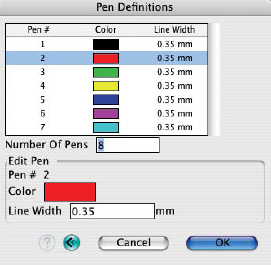
The HPGL Pen Definitions dialog.
Pen Definitions…: This button invokes the Pen Definitions dialog, shown in to the right. This dialog is used to define the pens that are available on a plotter. The top portion of this dialog is a scrollable list of defined pens. It shows the pen number, color, and line (pen tip) width. Clicking on a pen definition in this list will select it for editing. The bottom portion of the dialog contains fields that are used to set pen definitions.
Number Of Pens: This sets the number of pens the plotter has. The number of pen definitions shown in the list will match this number.
Edit Pen: This area contains fields for editing the definition of the selected pen.
Pen #: The numeric index of the selected pen (not editable).
Color: The color of the selected pen. Clicking on this item will pop up the Color Selection dialog and the pen color can be set in this dialog.
Line Width: The line (pen tip) width. The value in this field is always in millimeters.