Lights and shadows
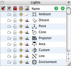
In form•Z, light sources can be defined as one of eight available types: distant, point, cone, projector (gel), area, custom, line, and environment. These are in addition to the ambient light that illuminates all surfaces equally. Light color and intensity of the ambient light are set in the Lights palette. They appear in wire frame and shaded display types when they are marked as visible in the Lights palette.
At start-up, form•Z automatically creates one distant light, representing the sun. In addition, a scene always contains one ambient light. Distant, point, cone, projector, area, custom, environment, and line lights and their names are displayed in the Lights palette. Lights can be defined and existing lights can be deleted or edited through the Lights dialog. The parameters and the positions of lights can be set in the Light Parameters dialog. Their positions can also be manipulated using the geometric transformation tools of form•Z. The ability to cast or not cast shadows at different quality levels is also available. The specific light functions are discussed in the remainder of this section
Lights may have different sets of parameters depending on the rendering mode used. RenderZone is a rendering plugin available for form•Z that allows for more realistic rendering of still images and animations complete with Global Illumination effects. It is installed with form•Z by default as a watermarked version for evaluation, even if it is not initially purchased. As a result, the RenderZone mode light parameters will be avaialable under the light Parameters tab even if you have not yet purchased the RenderZone rendering plug-in.
There are six tools in the Animation Workspace that allow you to quickly and easily define light sources.
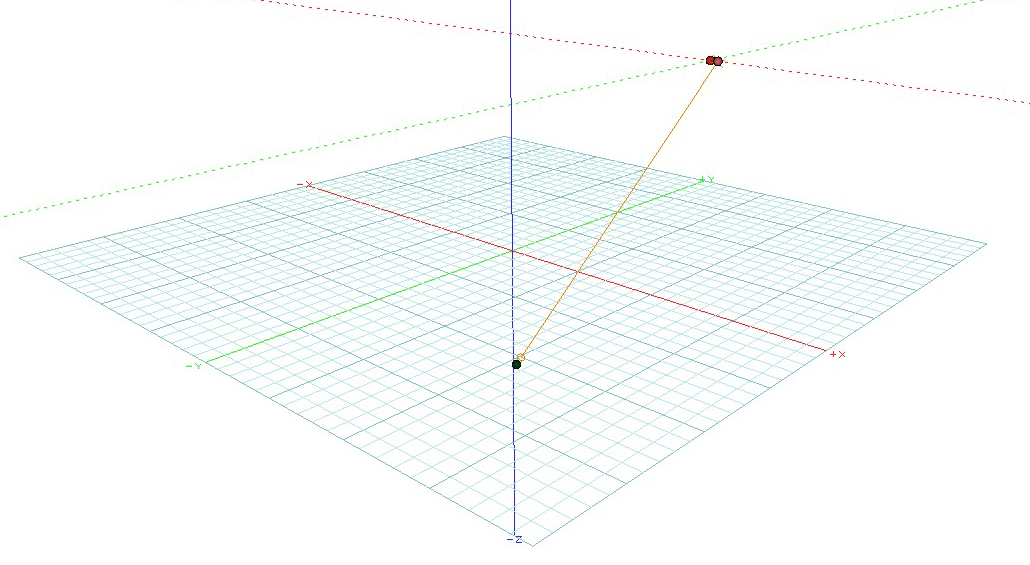
 Point Light
Placing a Point Light..
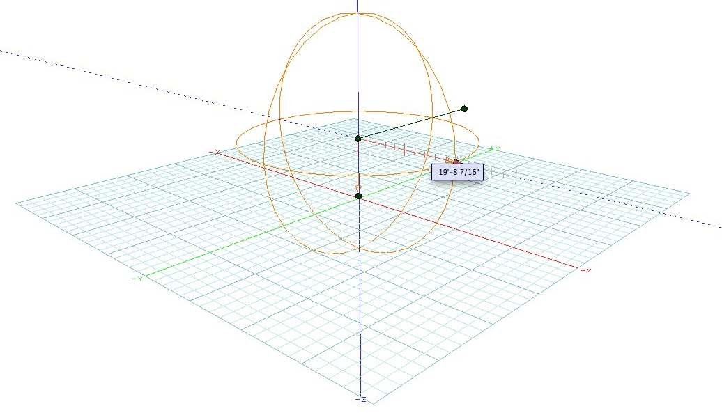
Point lights emit rays from a given point outward in all directions. The intensity of these lights may or may not decrease as the distance from the source increases, depending on the setting. An example of a point light is a candle.
With this tool active, each click in the modeling window places a new point light whose center is at the click point. After a point light is placed, an arrow widget is diplayed. Adjusting this arrow changes the radius of the light, which is a spherical surface visible in wire frame and shaded modes that defines where the intensity of a light matches the value set in the Brightness box in the Intensity tab.
 Cone Light
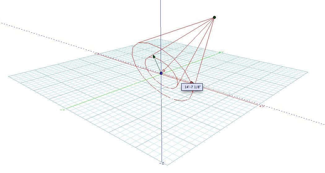
Placing a Cone Light..
Cone lights emit rays from a given point in the direction defined by their conic shape. The intensity of these lights may or may not decrease as the distance from the source increases, depending on the setings. The intensity of these lights also decreases at the perimeter of the cone. This area of decreased intensity is defined by a second cone inside the outer cone. Car headlights are an example of cone lights.
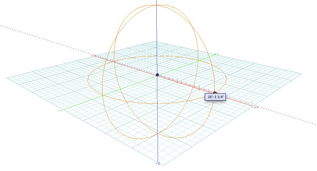
 Distant (Direct) Light
Placing a Distant Light.
Distant (or direct) light emits parallel rays from an infinitely distant light source, such as the sun. The intensity of this light remains constant throughout a scene. Atmospheric light, which simulates light from the sky and which is non uniform in direction can be added under the Parameters tab.
 Projector Light
Placing a Projector Light..
Projector lights emit rays from a given point in the direction defined by a pyramid that is associated with them. The intensity of these lights may or may not decrease as the distance from the source increases, depending on the setting. The rays emitted by such lights are also filtered through an image map, projecting that image onto a scene. An example of a projector light would be a slide projector.
 Custom Light
Placing a Custom Light..
Custom lights represent variable intensities in different directions about a light source. For example, a point light, which is used to represent a bulb hanging in a room is assumed to emit rays of equal intensity in all directions. However, light sources do not work this way in reality. A bulb has a higher intensity in the direction of the socket, and its intensity falls off toward the socket, and it is zero directly behind the socket. Custom lights take into consideration these real world “irregularities.” The intensity of these lights may or may not decrease as the distance from the source increases.
IES stands for Illuminating Engineering Society. The IES file format was created for the transfer and use of photometric data over the web. An IES file is basically the measurement of distribution of light (intensity) stored in ASCII format. You can think of it as a digital profile of a real world light. In form•Z it can be used for creating lights with shapes and physically accurate light casting attributes.
IES light files are created by many major lighting manufacturers and can be downloaded from their sites.
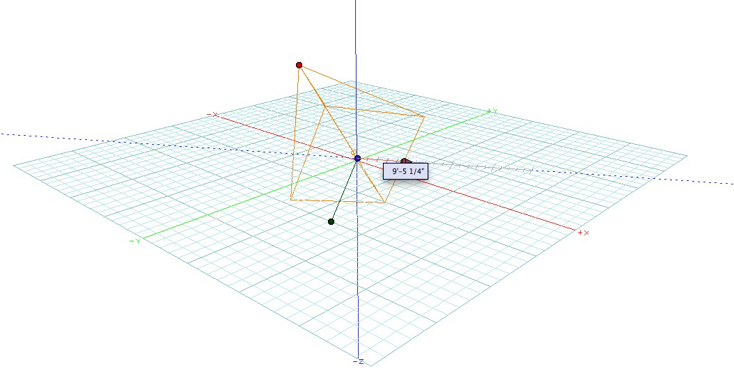
 Area Light
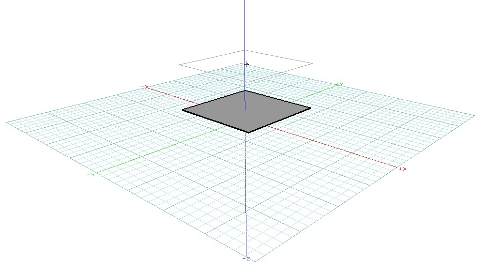
Creating an Area Light from a flat plane.
Area lights are associated with physical objects whose surfaces are emitting light. For example, it is possible to create a plane or other flat polygon and turn the resulting object into an area light. The intensity of these lights may or may not decrease as the distance from the source increases.
 Line Light
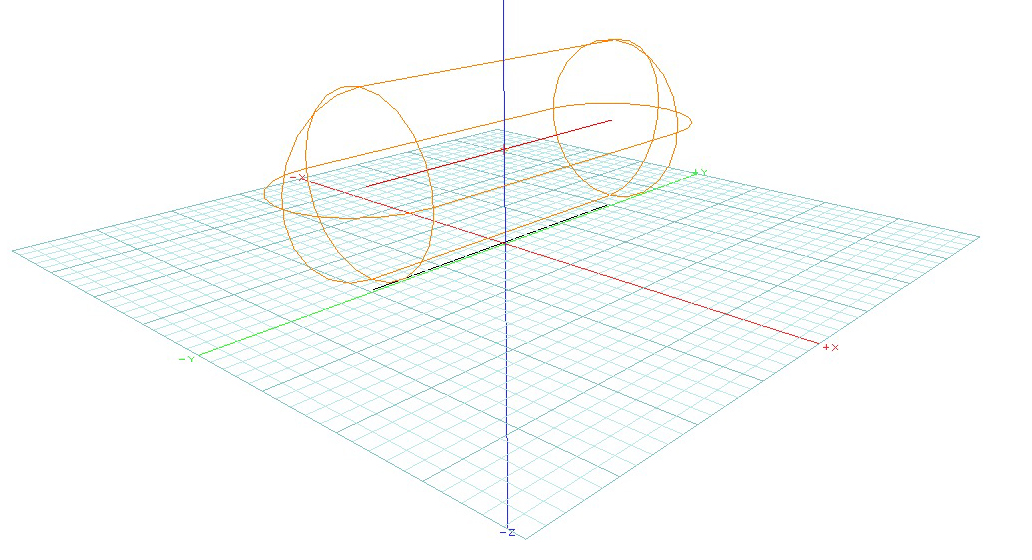
Creating a Line Light from an open wire.
Line lights are derived from and are associated with open or closed surface objects in the same way area lights are derived from surface or solid objects. However, the object of a line light is not rendered in the same way it is for an area light. Light rays are emitted from the segments of an object rather than the object as a whole. The intensity of a line light may or may not decrease as the distance from the source increases, depending on the settings.
The Lights palette and dialogs
The Lights palette.
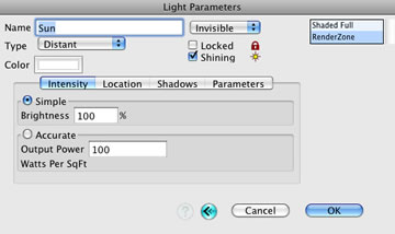
The Light Parameters dialog.
Lights can be defined and existing lights can be deleted or edited through the Lights palette. The parameters and the positions of lights can be set in the Light Parameters dialog. Their positions can also be manipulated using the geometric transformation tools. The ability to cast or not cast shadows at different quality levels is also available. The specific light functions are discussed in the remainder of this section.
All currently defined light sources are displayed in the Lights palette shown at right. If not open, this palette can be invoked from the Palettes menu in the usual manner.
Different icons are used to display the different light types, which are as follows: ambient, distant, point, cone, projector, area, custom, line, and environment.
The default type when new lights are created is distant. Double clicking on a light name in the Lights palette invokes the Light Parameters dialog, which allows you to change the attributes of a light.
The Light Parameters dialog looks different when the RenderZone mode is selected. On the upper right is a list with rendering modes. One is active and shows those light parameters that are relevant for that rendering mode. For example, if RenderZone is selected, the more complex parameters applying to it are shown, as opposed to the simpler parameters shown when Shaded Full is selected.
To accommodate additional parameters, the dialog is organized in four tabs: Intensity, Location, Shadows, and Parameters. The Light Parameters dialog contains four tabs, discussed next. Note that the exact content of each tab depends on the type of light that is currently selected.
Intensity tab
This group of options allows you to set up the intensity of lights and their falloff through more or less detailed methods, depending on the type of light.
Falloff: This menu allows you to select how the intensity of the light will decrease as the distance of the light from an illuminated surface increases. Five options are available, all of which use different formulas to compute the light intensity of a surface pixel when illuminated by a light source.
When the Simple intensity option is chosen, the radius parameter (point, custom, area, line lights) or the distance from the light’s origin to the light’s center of interest (cone, projector lights) is taken into account for the intensity calculation. This distance will be identified as r in the description below.
Constant: The light intensity of a surface pixel is the same anywhere in the scene.
Linear Clamped: The light intensity of a surface pixel is the same as the value entered in the Simple field, if the surface pixel is at a distance of r from the light source. If the pixel is further away, the intensity decreases linearly. For example, if the Simple intensity is set to 100% and the pixel is twice as far as r, the intensity is 50% (100 % / 2). If the pixel is eight times as far way as r, the intensity is 12.5% (100 % / 8) If the pixel is closer than r, the intensity increases approximately linearly, but will not exceed a maximum value. For example, if the pixel is half as far away as r, the intensity is about 200% (100 % / 0.5). However, as the pixel gets closer to the light source, the intensity does not increase linearly anymore and is clamped against a maximum value. This will guarantees, that a pixel very close to the light source will not get an unreasonably high illumination and avoids unexpected overexposure in a scene.
Square Clamped: The light intensity of a surface pixel is the same as the value entered in the Simple field, if the surface pixel is at a distance of r from the light source. If the pixel is further away, the intensity decreases with the square of the distance. For example, if the Simple intensity is set to 100% and the pixel is twice as far as r, the intensity is 25% (100 % / (2 * 2)). If the pixel is eight times as far way as r, the intensity is 1.5625% (100 % / (8 * 8)). If the pixel is closer than r , the intensity increases approximately with the square of the distance, but will not exceed a maximum value. For example, if the pixel is half as far away as r, the intensity is about 400% (100 % / (0.5 * 0.5)). However, as the pixel gets closer to the light source, the intensity does not increase with the square anymore and is clamped against a maximum value. This will guarantees, that a pixel very close to the light source will not get an unreasonably high illumination and avoids unexpected overexposure in a scene. Square falloff is a physically accurate representation of a light’s illumination as long as the pixel intensity is not clamped at a closed range, as described above.
Linear Unclamped: This is the same as the Linear Clamped option, with the exception, that the intensity at pixels which are closer than r away from the light source is not clamped. Therefore these pixels may get overexposed easily. If this is not desirable the Linear Clamped option should be used.
Square Unclamped: This is the same as the Square Clamped option, with the exception, that the intensity at pixels which are closer than r away from the light source is not clamped. Therefore these pixels may get overexposed easily. If this is not desirable the Square Clamped option should be used. Square Unclamped falloff is the physically most accurate representation of a light’s illumination.
When the Accurate intensity option is chosen, the radius or distance parameters of a light are not used to determine the intensity. The Photometric or Radiometric intensity in the Accurate Intensity option serves as the basis for the illumination calculation. When rendered, the computer screen serves as the photo film in a camera which is exposed by the light source. The film’s sensitivity is set in such a way, that an interior scene with a number of average brightness light bulbs is well exposed. Under and over exposed images can be corrected with the Exposure Correction option as described in Section 1.10. Note, that the Falloff menu is available for both, Simple and Accurate intensity. For a physically accurate exposure, it is necessary to choose the Square Unclamped falloff option. However, to generate visually pleasing images physically accurate illumination is often times not desirable and therefore the Accurate intensity option may very well be combined with different falloff methods.
Simple: When this option is selected, the value entered in the Brightness field determines the intensity of the light, expressed as a percentage. While this parameter is entered in the same way for all types of lights, its application to the different types varies, as follows:
Ambient, distant, environment: These lights always have a constant intensity and the intensity value is applied uniformly.
Point, custom: When Constant is selected for this light from the Falloff menu, its intensity remains uniform throughout. If a Linear or Square falloff is selected, the value entered in the Simple field is applied to the points of the spherical surface defined by the Location of the origin of the light and the value entered for Radius (see section 5.3). The light intensity increases between the spheric surface and the origin of the light. It decreases as it moves away from the spheric surface (at distances from the light origin greater than the Radius). The degree at which the light intensity increases or decreases depends on whether Linear or Square falloff has been selected. The distribution for point light is uniform in all directions, while the intensity distribution of a custom light is dependent on the parameters defined in the Intensity Distribution dialog (see Figure 5.6.5). This is discussed in detail in subsection 5.6.
Cone, projector: When Constant falloff is selected for these lights, their intensity remains uniform throughout. If Linear or Square is selected, the value entered for Simple is applied at the Center Of Interest (see next section). The intensity increases between the light’s origin and the center of interest, and decreases beyond the center of interest at a rate dependent on whether Linear or Square falloff has been selected.
Area, line: When Constant is selected for these lights from the Falloff pop up menu, their intensity remains uniform throughout. If a Linear or Square falloff is selected, the value entered in the Simple field is applied to all shaded points that have the same distance as the Radius (see section 5.3). The light intensity increases between these points and the light source. It decreases as it moves away from these points (at distances from the light source greater than Radius). How the light intensity increases or decreases depends on whether Linear or Square falloff is on.
Note that when a surface is in the area where the intensity of a light increases, there is always a risk of overexposure. If such an effect is not desirable, then a Constant intensity should be used.
Accurate...: When this option is selected, the intensity of the light is described through physically accurate units. The Accurate Intensity parameters are shown in the area below the option. They vary between the different light types. The Accurate Intensity parameters for distant lights are unique. The other seven types of light share similar parameters. However, the Brightness parameter for cone and point lights can be defined using either lumens or candelas. Only lumens can be used to set the brightness of area, line, environment, and custom lights. Achieving accurate intensity for the different types of lights is discussed in more detail in subsequent sections.
Location tab
This group of options contain the Origin and Center Of interest of a light. You can also use the dropdown menu to choose light direction By Site, Date, and Time, or by Altitude and Azimuth. These alternate methods of determining light direction allow for solar studies and evaluating the shadows cast by an object at cetrtain times of day at different locations on the Earth. There is also a Sun Animation extension under the Extensions menu. The controls for this extension are similar to the Sun settings under the Location tab of a light's dialog.
Shadows tab
This group of options specifies if the light casts a shadow and what type of shadow it casts. Shadows are cast when the Shadows box is checked, but additional options in other dialogs need to be set as well, as discussed in detail below.
The type of shadow is set in the menu below the Shadows check box:
Type: Soft (Mapped), Hard (Raytraced), Hard (Accelerated): When one of these items is selected, shadows are created through shadow maps, raytracing, and a combination of raytracing and shadow maps, respectively. In the latter case, shadow maps are used to accelerate the generation of raytraced shadows, which has additional memory requirements.
Transparent: This option is only available when raytraced shadows are generated. When on, a light generates transparent shadows when shining through transparent surfaces. Such shadows take longer to render, even if there are no transparent surfaces in a scene. A rendering can be accelerated by turning this option off, if there are no transparent surfaces visible, or if the light does not illuminate any transparent objects. Recall that if the Per Light item is chosen from the Shadows menu in the RenderZone Options dialog, the Transparency shadow option in each individual light source is considered. If the All Opaque or All Transparent option is chosen from the menu, the Transparency option for each individual light is overwritten.
In RenderZone, objects in a scene can cast shadows when the z-buffer or raytrace display method is used from the Rendering Type menu in the RenderZone Options dialog. For shadows to be cast, the following parameters must be set properly:
-
The shadow attribute of an object must be on. It is on by default when a new object is created.
-
-
The shining attribute must be turned on for at least one light (other than ambient lights). This attribute is turned on in the Light Parameters dialog and in the Lights palette.
-
-
The Shadows option must be selected for this light in the Light Parameters dialog, and the type of shadow (Soft (Mapped), Hard (Raytraced) or Hard (Accelerated)) must be selected from the Shadows pop up menu. More than one light can cast shadows at the same time, but only those lights whose shining and shadow parameters are on will.
-
-
The Shadows option in the RenderZone Options dialog must be turned on when the RenderZone* command is executed. Recall that this dialog can be invoked directly from the RenderZone* menu item before executing the operation.
When the Soft (Mapped) (default) type of shadows is selected from the Type menu, additional options that affect the quality of the shadow can be selected from the Shadows tab. Shadow casting in general adds a significant amount of computation time to the rendering of a scene. When using soft shadows, the higher the quality of the shadow, the longer it will take to complete the rendering. Consequently, it is generally recommended that lower qualities of shadows be used initially and the higher quality shadows be used for a final rendering. Each additional light adds to the time required for a rendering and consumes additional memory. In general, soft shadows require significant quantities of memory but are faster than hard shadows.
Quality: A Low, Medium, or High quality of shadow can be selected from this pop up menu. Low quality requires less time and less memory, but may show noticeable jaggies at the perimeter of shadows. High quality shows less jaggies, but requires more time and memory.
Softness: This sliding bar controls the smoothness of the edges of the shadows. Zero (0) softness produces the hardest shadow edge, while 100 produces the fuzziest edge.
Tolerance: This parameter is used to eliminate self-shadowing artifacts. Note that when the Softness parameter is increased, it is possible that a surface casts shadows on itself. This artifact manifests itself as random patterns of darker pixels on that surface. Increasing the Tolerance parameter reduces these artifacts. Note, however, that high Tolerance values may cause the shrinking of the area of a shadow. In some cases this will create the effect of an object floating above a plane, although the object is placed directly on the plane.
Resolution: Soft shadows for Shaded Render* and RenderZone* are generated by producing a shadow map for each of the shadow casting light sources before any rendering occurs. These maps are then used during rendering to determine whether a pixel is in a shadow region or not. Shadow maps can be produced at different sizes (levels of resolution).
If the n Times Image Size option is selected, the resolution of the shadow map depends on the size of the image at the time the rendering is executed. If, for example, the image size is 500 x 500 pixels and a value of 2 is entered, the shadow map is generated at a resolution of 1000 x 1000 pixels. Choosing this option guarantees that the quality of the shadows is the same even if the window is resized between individual renderings. If the m by n Pixels option is selected, the shadow map is created at a fixed resolution, defined by the value entered in the text field. This option guarantees that the memory consumption fo r the shadow map is the same for each rendering, regardless of the image size. However, if the image size is increased, the shadow quality may decrease.
Limit Map To: One of three available items can be selected from this pop up menu, which determines whether objects outside the view will cast shadows. This selection affects the size of the shadow maps and the quality of the shadows cast in an indirect way.
All Objects: When this option is selected (default), the shadow map is generated for all the objects in the project that cast shadows, even those that are completely out of the view.
All Completely Visible Faces: When this option is selected, only the faces which are entirely visible in the screen are used to determine the shadow map.
All Completely Visible Objects: When this option is selected, only the shadow casting objects that are completely visible in the displayed view will be used to calculate the shadow map. The last two options can increase the crispness and quality of the shadows significantly, but will produce inaccurate shadows whenever objects that are not visible in the window cast shadows on objects that are visible.
Warnings: As already noted, soft shadows are generated by producing a shadow map before any rendering is executed. This shadow map includes all the objects that are set to cast shadows, regardless of whether or not they actually do. For example, a more or less flat ground plane with the sun above it does not produce any shadows, even though it accepts shadows from other objects that may be sitting on it. If such a ground object is significantly larger than the objects that actually cast shadows, a shadow map which is calculated at the size of the screen will only contain a small portion of shadows. If a close up rendering containing only the smaller objects that cast shadows is produced, the shadows will be fuzzy. This is because the small portion of the shadow map that contains the shadows is magnified to (possibly) fill the screen. This causes the edges of the shadows to lose their crispness. To avoid this, when a scene contains objects such as ground planes that do not cast shadows, the shadow attribute of these objects should be turned off. In general, crisp soft shadows are achieved when the size of the shadow map is close to the size of the rendering. For crisper shadows, you should avoid objects which either do not cast shadows or which are outside the view and therefore cast shadows which will not be visible. This will not only produce crisper shadows, but it will also render faster. These distinctions are illustrated below.
a
|
b
|
|---|---|
c
|
d
|
Soft (Mapped) shadows: (a) A scene with a huge ground object. (b) The part that wil
l be rendered. (c) When large ground object casts shadow, shadow quality is poor. (d) Turning off shadow
attribute of large ground object produces crisp shadows.
These considerations should be made in conjunction with the Limit Map To options. If there are objects outside the view that do not cast shadows on visible objects, then the All Completely Visible Faces or All Completely Visible Objects option should be selected. This will result in smaller shadow maps and thus crisper shadows.
The shadow maps used for the generation of Soft shadows can be very memory intensive, and should be used conservatively if your machine has a relatively limited amount of memory. For each pixel in a shadow map, 4 bytes of storage is required. For example, a shadow map of 500 x 500 pixels requires 1 Megabyte of memory. Assuming a constant shadow map size, cone and projector lights generate the best shadow quality, compared to the distant, point, and custom lights. Point and custom light shadow maps have the highest memory requirements, which is six times more than that required for cone, projector, or distant lights. Given that a separate shadow map needs to be produced for each light, using too many shadow-casting lights increases the risk of running out of memory. Note that area and line lights do not offer the option to use shadow maps. They only cast raytraced shadows.
Hard (Raytraced) shadows do not use shadow maps, but rather ray tracing procedures. Distant, point, custom, cone, and projector lights produce crisp raytraced shadows. Area and line lights create soft raytraced shadows. Their memory requirements are minimal, but they generally require more processing time.
Hard (Accelerated) shadows are raytraced but also use shadow maps to speed up the raytracing procedures. Their memory requirements are the same as soft shadows.
The type of shadow used in a rendering scene depends on the effects a user wishes to achieve. Shadows are attributes of the light, and their type is set independently for each light, which allows you to mix the two types of shadows within the same rendering scene.
Parameters tab
Common options
Lens Flare: This option determines whether the light is able to cause lens flares during the RenderZone postprocess lens flare operation, which is discussed in the corresponding section if the RenderZone manual.
Glow: When this option is on, the light displays a glowing volume when rendered in the z-buffer and raytrace rendering modes. It is discussed in more detail in the RenderZone manual.
Glow Options...: This button invokes the Glow Options dialog, this is discussed in detail in the RenderZone manual.