Faceting Schemes
Smooth objects, in addition to their smooth surface representations, also carry faceted approximations, also known as polygonal representations. A facet is a planar polygon that is typically triangular or rectangular. A set of such facets is used to approximate the complete surface of a smooth object. The facets may be visible when the wire frame method is used to display the object (see next section) and becomes the sole representation of an object when it is converted from smooth to faceted.
The faceting of a smooth object may be at different levels of resolution and may be generated on the basis of different faceting criteria. A user can select unique parameters when a faceting is generated or may use one of the existing faceting schemes. A faceting scheme is a set of parameter values that have been preset for the faceting algorithm.
A smooth object is faceted at the time it is created, using the faceting parameters found in the Display Resolution section of its Tool Options palette. The Tool Options palettes of all the tools that generate smooth objects contain such a section. The faceting parameters may be set before an object is generated and they can be further adjusted after the object is generated and while it is in the result buffer. The facets of a smooth object can also be changed at a later time by selecting it with the Pick tool and then activating the Attributes tab in the Pick Tool Options palette, which contains a Display Resolution section.
The Display Resolution section of the Tool Options palettes offers two methods for setting the faceting resolution of an object: Simple and Scheme.
Simple is a sliding bar ranging from 0 to 100%, representing a preset lowest and highest resolution. You can slide the bar or type a new numeric value in its field. If an object is displayed in wire frame and is in the result buffer or selected with the Pick tool, when you apply these changes, you can observe the changes shown graphically.
Scheme is a popup menu that contains the names of a number of preset schemes. Selecting one of them applies the respective resolution scheme to the object, whose change you can again observe graphically. At the bottom of the popup list is the Faceting Schemes... item. Clicking on it invokes the Faceting Schemes dialog where you can define your own schemes.
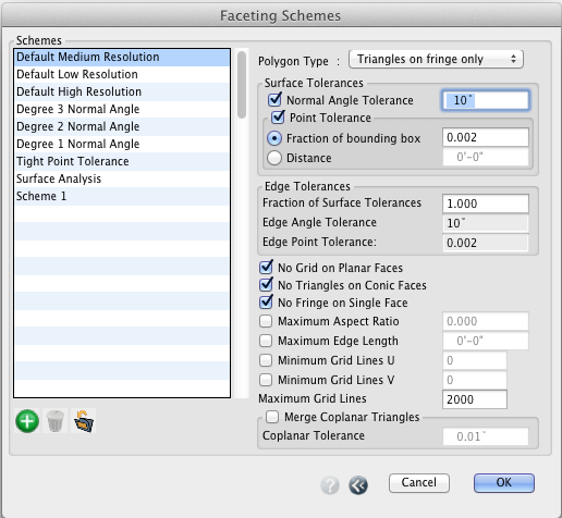
The Faceting Schemes dialog.
The Faceting Schemes dialog contains a list of predefined schemes on its left side. There are 8 schemes provided by form•Z. The user can add any number of custom defined schemes. To do so you click on the New Scheme (![]() ) button under the list. The program generates a name, which you can change. You can then proceed and set the parameters you desire on the right side of the dialog. You can also delete a scheme by selecting it and then clicking the Delete Scheme button.
) button under the list. The program generates a name, which you can change. You can then proceed and set the parameters you desire on the right side of the dialog. You can also delete a scheme by selecting it and then clicking the Delete Scheme button.
When you select the name of a scheme, its parameters are displayed on the right side, where you can inspect them and also change them. They are as follows:
The Polygon Type popup menu contains 4 items that determine the structure of the faceting: All Triangles generates a quad-tree mesh with triangulated face boundaries and triangulated interior quads. Triangles On Fringe Only is a quad-tree mesh with the boundaries triangulated. No triangles, Full Grid is a single grid with no subdivisions and no triangles. No Triangles, Quad-Tree is a quad-tree mesh, all subdivided quads and no triangles.
The Surface Tolerances group of options sets certain conditions that need to be satisfied when a faceting scheme is generated.
Normal Angle Tolerance sets the maximum angle allowed between surface normals at adjacent points on the facet mesh.
Point Tolerance is the maximum distance between a point on the original surface and a mesh segment. It can be defined through one of two methods: Fraction Of Bounding Box defines the distance as a decimal fraction of the length of the diagonal of the object’s bounding box. Thus, with this option, the size of the object affects the point tolerance. In contrast, with Distance the tolerance is given as an absolute distance, which makes it independent of the size of the object.
The Edge Tolerances group of options specify conditions for the edges.
Fraction Of Surface Tolerances is a ratio of edge to surface faceting tolerances. For example, suppose it is set to 0.5 and the surface Normal Angle Tolerance is set to 10 degrees. Then the edge faceting will have an angle tolerance of 10 x 0.5 = 5 degrees.
Edge Angle Tolerance and Edge Point Tolerance as for the surface tolerances, above.
The remaining options offer choices that affect different details of the faceting scheme:
No Grid On Planar Faces: When on, planar faces of objects are not subdivided, regardless of the other parameter settings. Only non-planar faces will be subdivided.
No Triangles On Conic Faces: When on, all conic faces of an object will be faceted with quads, regardless of other settings.
No Fringe On Single Face: By default, face boundaries are triangulated. With this option on, the boundary of an object with a single face will not be triangulated.
Maximum Aspect Ratio: When on, it specifies the intended maximum aspect ratio of a quad facet in 3D space.
Maximum Edge Length: Specifies the maximum length of a facet edge.
Minimum Grid Lines U, Minimum Grid Lines V: Specify the minimum numbers of constant U and constant V grid lines per face.
Maximum Grid Lines: Specify the maximum grid lines in U or V.
Merge Coplanar Triangles: When on, coplanar triangles are merged, where the planarity level is set in the Coplanar Tolerance field.