Cone of vision
The Cone Of Vision command at the end of the View menu opens the Cone of Vision window, through which views can be set. This is a special type of a graphics window that is subdivided in four areas, each occupying one quarter of the screen. Three of these areas function as associated windows and display orthographic projections: top view in the upper left portion, front view in the lower left, and right view in the lower right. These views display the modeling scene as well as the cone of vision with its controls, which can be moved in any of the three orthographic projections. The upper right area displays the 3D view, referred to as the preview area.
The Cone of Vision window works like a dialog; it remains the only active window until it is closed. When it is first opened, the upper left projection is active. Any other projection may be activated by clicking on it. The active area is marked by a red frame. The Cone of Vision window has most of the features of a common window, but it can not be resized or moved. It has a close box and clicking on it closes the Cone of Vision window, and returns control to the graphics window that was active at the time the Cone of Vision window was opened. The view shown in the preview area becomes the current view in the active window.
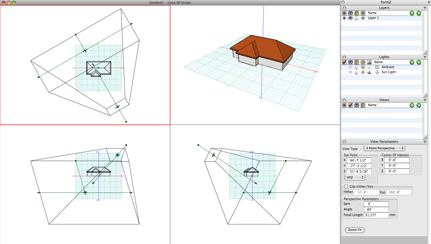
The Cone of Vision window for a perspective view.
Most of the general menu bar commands remain available and can be used while the Cone of Vision window is active. They mostly affect the preview area. Also, navigation operations executable with mouse buttons are available to the projection areas.
A number of palettes are useful in the Cone of Vision. These palettes are found in a special dock that is present to the right of the Cone of Vision window. The Layers, Lights, Views, and View Parameters palettes are in this dock. As the cone is graphically edited, the parameters are updated real-time in the View Parameters palette.
When hitting the Zoom Fit button at the bottom of the View Parameters palette, the view is changed so that all objects in the scene are shown in the view and the Cone of Vision is adjusted accordingly.
All the parts of the cone of vision act as controls and can be moved in the active projection. Moving controls of the cone causes one or more of the viewing parameters to change. To move a control, click and drag the mouse. This rubber bands the affected portions of the cone and the image in the preview area is constantly updated, allowing you to visually inspect the result of the movement. When you are satisfied with the new view, one more click of the mouse freezes the view at its current state. The process of editing the view may continue by picking the same or another control of the cone of vision, in the same or another area. Picking a control in another area first activates that area, then picks the intended control and begins to move it. The controls are as follows, where the indices are also marked on the illustration:
(a) The viewer position is the small bullet that represents the eye of the viewer. It is connected to the center of interest and the two together define the line of sight (see below). When the viewer position is moved, the line of sight is anchored at the center of interest. The viewer position may be moved along the length of the line of sight or it may be rotated around the center of interest, which affects the direction of the line of sight. The complete cone of vision follows the motion. The line of sight is always the central axis of the cone of vision and perpendicular to it are the yon and hither planes.
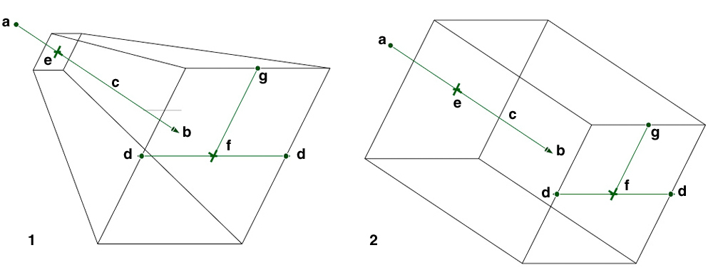
Controls of the cone of vision for (1) perspective and (2) axonometric: (a) viewer position, (b) center of interest, (c) line of sight, (d) view angle, (e) hither plane, (f) yon plane, and (g) view spin.
(b) The center of interest is picked by clicking the mouse on the small arrow at the end of the line of sight. When it is moved, the line of vision remains anchored at the viewer position. It may move along the direction of the line of sight or it may rotate about the viewer position. Its movement affects the complete cone of vision in the same fashion as the movement of the viewer position.
(c) The line of sight is the line connecting the viewer position and the center of interest. It is selected by clicking the mouse on or close to it. When the line of sight is moved, both the viewer position and the center of interest move together. Thus the line of sight is always moved in directions parallel to its original position. Again, the motions of the line of sight affect the complete cone of vision.
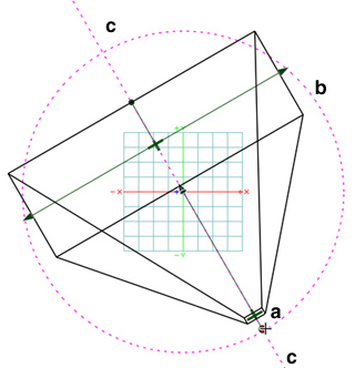
The top view window for the cone of vision: (a) viewer position,
(b) viewer position circle guide, and (c) line of sight guide.
The movement of the viewer position (a), or center of interest (b) can be constrained to move along the Line of Sight by snapping it to the linear guide which appears as soon as the control is dragged.
In the top view window the viewer position (a) may also be constrained to a circle around the center of interest (b) by snapping it to the circular guide. This gives the effect of the view moving around the center of interest at the exact same distance at a constant height.
(d) The view extent or view angle is picked by clicking the mouse on one of the arrows at the bottom of the cone and behaves differently for each type of cone. In the cone for axonometric, isometric, and oblique, all four edges move parallel. This motion increases or decreases the view extent. Reducing the view extent results in a larger image and increasing it results in a smaller image. In the perspective cone, all four edges move together symmetrically, following the motion of the selected line. This motion increases or decreases the view angle. Reducing the view angle results in a larger image and increasing it results in a smaller image.
(e) The hither plane is picked by clicking the mouse on the cross mark at the top face of the cone, which represents the position of the hither plane. The hither plane moves only along the direction of the line of sight and cannot be moved beyond the current position of the yon plane or beyond the eye position. The hither plane represents the nearest visible point along the line of sight. When the Clip Hither/Yon option is selected, the rendered and hidden line images are clipped to this plane. Objects or portions of objects that are in front of this plane are invisible when clipped.
(f) Similarly, the yon plane is picked by clicking the mouse on the cross mark at the bottom face of the cone, which represents the position of the yon plane. The yon plane moves only along the direction of the line of sight and cannot be moved closer to the viewer position than the hither plane. The yon plane represents the farthest visible point along the line of sight. When the Clip Hither/Yon option is selected the rendered and hidden line images are clipped to this plane. Objects or portions of objects that are behind this plane are invisible when clipped.
(g) The view spin is changed by clicking the mouse on the bullet at the bottom of the cone. When picked, the cone is dynamically rotated around the line of sight. This has the effect of tilting the viewer’s head and looking at the modeling environment sideways. The bullet is connected with a straight line to the center of the yon plane. This line represents the “up” direction of the view. It is parallel to the vertical sides of the image.
As already mentioned, many of the menu bar commands remain available to the Cone of Vision environment and can be used, with their action being frequently adjusted to the semantics of the cone of vision. For example, the Undo and Redo items affect the view manipulations that have occurred within the cone of vision environment. All the display and the view type setting commands affect the 3D preview area only and none of the three projection areas. The Synchronize command can be used to align and scale the views of the cone of vision three projection areas.