Layout
The Layout dialog.
Layout is an environment within form•Z that is used for the preparation of drafted documents of projects based on sheets. In layout mode, the graphics environment is 2D and the working surface is the sheet. The drawing is created by placing views of a 3D model at specific scales and specific locations on the sheet. These graphic representations are linked to the original model so that, as the model evolves, the layout can be automatically updated.
Additional graphic elements can be added in the layout including line work, shapes, dimensions, hatches and images. The graphic images of the model can be edited to make any required 2D changes to the drawing. Form•Z layout projects are stored in a project file with an .fml extension.
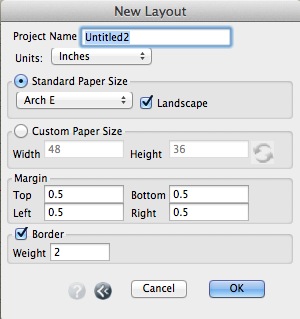
Selecting the New Layout Project item from the File menu creates a layout project. This invokes the New Layout dialog that is used to define the parameters of a layout. The Name of the layout project is the name that will be used when the project is saved. The Units are defaulted to Inches or Centimeters depending on your computer's settings.
Layouts are based on a specific paper size. All sheets in the layout use the same paper size. The Standard Paper Size menu lists a number of commonly used paper sizes. The Landscape option orients the paper horizontally and is on by default. The Custom Paper Size options are available so that you may use a sheet size that does not appear in the Standard Paper Size menu.
The Margin settings define the border around the physical edge of the paper in which nothing is printed. The margin settings can be used to limit the printing for aesthetic reasons, but also it is important to note that most printers cannot print to the edge of the paper. So you should select a margin that reflects the printer's characteristics.
The Border option causes a border line of the desired Weight to be drawn around each sheet, just inside the margin.
When the options are complete, the new project is created with a single sheet as a starting point. The graphic window shows a display of the sheet. The form•Z workspace is transformed into an environment that offers the tools and palettes that are useful for layout tasks. A number of menu items and standard tools will appear dimmed, as they are not available in the layout workspace.
The Layout options can be changed, after the project is created, in the Project Settings dialog, invoked from the File menu. The Layout tab contains all of the same options as the New Layout dialog. Note that changing the paper size after a drawing has been created can cause the drawing to be disturbed if the paper size changes cause elements in the drawing to collide or be arranged on different pages.
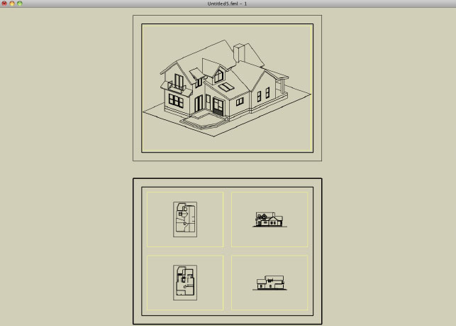
A Layout with two sheets.
Layout Tools
The Layout tool palette contains a subset of the form•Z tools. These are the tools that are appropriate for creating documents in the layout environment. Note that some tools have options that are not appropriate for the layout environment. For example, the Move tool and all the transformation tools do not have the options for parallel or perpendicular to reference plane motions, as in layout the working plane is always the sheet.
There are four tools that are unique to the layout workspace. They are in the layout tool suite, in the third row of tools, in the layout workspace.
 Place Frame
A frame is a graphic reference to a 3D form•Z model (or bonzai3d model). That is, it displays a 3D model with a defined view and scale using specific characteristics to create drawings of the model. The frame retains the link to the model so that, as the model evolves, the drawing can be updated.
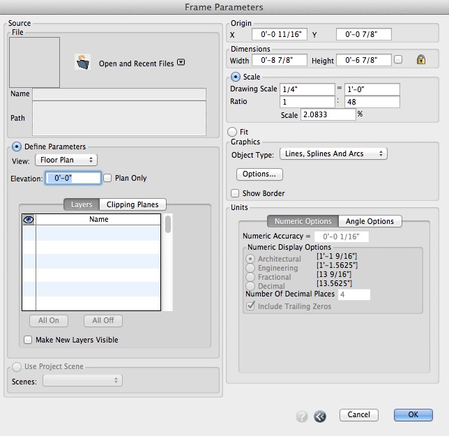
The Frame Parameters dialog.
This tool has an empty Tool Options palette, but invokes the Frame Parameters dialog, as soon as a rectangle representing the location and size of the frame is drawn. The first click defines one corner of the frame. As the mouse is moved, the opposite corner of the rectangle is defined by the cursor's location. A second click completes the operation. From the Frame Parameters dialog invoked you select a 3D model and other parameters.
The File section specifies the model file. The image is selected by clicking on the Open icon (![]() ) and then selecting the desired image file from the File Open dialog. A preview of the model is shown to the left of the Open icon. The Name and Path for the model file are shown below the icon, once a file is selected.
) and then selecting the desired image file from the File Open dialog. A preview of the model is shown to the left of the Open icon. The Name and Path for the model file are shown below the icon, once a file is selected.
When Define Parameters is selected, the characteristics (View, Layers, Clipping Planes, etc.) of the frame display can be configured as follows:
View: This menu determines the view of the model used in the frame display. This menu contains three groups: plan and section, standard projection views, and project views, whenever they have been saved with the project. Note that each item selected from the View menu is supported with its own set of options.
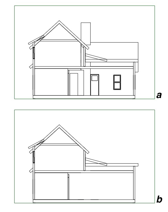
When Floor Plan is selected, the display is generated as a traditional top down floor plan. The plan is generated as a section through the model looking down at the specified Elevation. By default objects that are below the plane elevation are displayed as well unless the Plan Only option is selected. When this option is enabled, only the objects that intersect the elevation plane are shown. See example below.
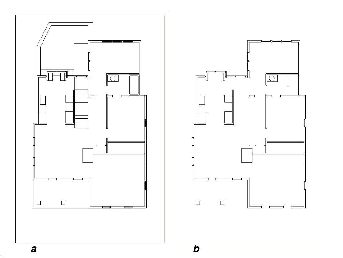
Two Frames: (a) without Plan Only and
(b) with Plan Only
When Section is selected, the display is generated as a section of the model. The section is generated looking directly at a clipping plane defined in the model. The Section Plane menu lists all of the clipping planes in the model. If there are no clipping planes in the model, then the Section option is dimmed in the menu. By default objects that are beyond the clipping plane are displayed as well unless the Section Only option is selected. When this option is enabled, only the objects that intersect the elevation plane are shown. See example below.
Two Frames: (a) without Section Only and (b) with Section Only
The standard projection views group offers options for the standard Top, Bottom, Right, Left, Back and Front views. The project views group is at the bottom of the menu and lists all of the views saved in the project (if any).
The Layers tab is used to control what layers are on in the frame display. The lists show all of the layers in the project. The first column shows an eye graphic (![]() ) to indicate that the specified layer is enabled. When the layer is enabled, objects on the layer are included in the display and they are excluded when the layer is not enabled (i.e. no eye graphic). By default, the layer is enabled, if it was enabled when the model was added to the project the first time.
) to indicate that the specified layer is enabled. When the layer is enabled, objects on the layer are included in the display and they are excluded when the layer is not enabled (i.e. no eye graphic). By default, the layer is enabled, if it was enabled when the model was added to the project the first time.
The Clipping Planes tab is used to control what (if any) clipping planes are enabled for the display. Clipping planes are explicitly used for section views, however they can also be useful in 3D views. The first column shows a red dot ( ) to indicate that the specified clipping plane is enabled. By default, no clipping planes are enabled.
The All On and All Off buttons can be used to turn all the layers or clipping planes on or off respectively.
Make New Layers Visible is an option in the Layers tab. This controls how layers that are added to the project after the initial creation of the frame are handled when the 3D model is changed and the frame is regenerated. When this option is enabled, the objects on the newly added layers are included in the frame. When the option is off, they are excluded.
Use Project Scene: When selected, the characteristics (view, layers, clipping planes, etc.) of the frame display are determined by a scene stored in the project. The Scenes menu displays a list of the scenes from the Scenes palette of the model file. The selected scene will be used for the frame display.
Origin: This is the X and Y coordinates of the lower left corner of the frame on the sheet.
Dimensions: This is the Width and Height of the frame on the sheet.
Scale: When selected these options determine the scale that is used to display the model in the frame. That is, the scale that is applied to the model to display it on the sheet. For convenience there are three methods of specifying the scale: Drawing Scale, Ratio and simple Scale %. These methods all represent the same internal scale factor and when any one is changed, the others are updated in kind. Depending on the scale, the view and the model itself, the image of the model may exceed the drawn frame. In this case the image is clipped by the edges of the frame.
When Fit is on, the model is fit to the frames extents. That is, the model is scaled to fit inside of the frame instead of following a specific scale.
Graphics is a group of options that control how the image of the 3D model is converted to the layout. The Object Type menu offers three options. With the Lines option, each edge of the model becomes a line in the layout. This is how prior versions worked. With the Poly Lines option, touching edges of each object are joined together to form chains of lines (poly lines). With the Lines, Splines and Arcs option, the edges of each object are analyzed to form the best matching geometry for the shape of the object. Note that the later two options create smaller files and when Arcs are created they can be dimensioned with the Radial Dimension tool.
The Options button invokes the Hidden Line Options dialog that is used to control the Hidden Line renderer that is used for the conversion from the 3D model to the layout graphics. For details on these options, see Hidden Line.
Show Border controls the visibility of the Frame border.
Units: This section offers options to select the type of units of measurement (English or Metric), the accuracy, and the format in which numbers and angles are displayed in the frame. These options are the same as the Project Working Units that can be found in the Project Settings section.
Editing Frames
Frames can be graphically edited by enabling the controls on the frame. This is done by selecting Show Controls in the context menu, which is invoked by selecting the frame with the Pick tool and then right clicking. Frames have nine controls that represent the corresponding corners, edges and frame center. Moving the center control moves the entire frame. Moving the corners and edges changes the cropping (clipping) of the frame, keeping the placement consistent. See example below.
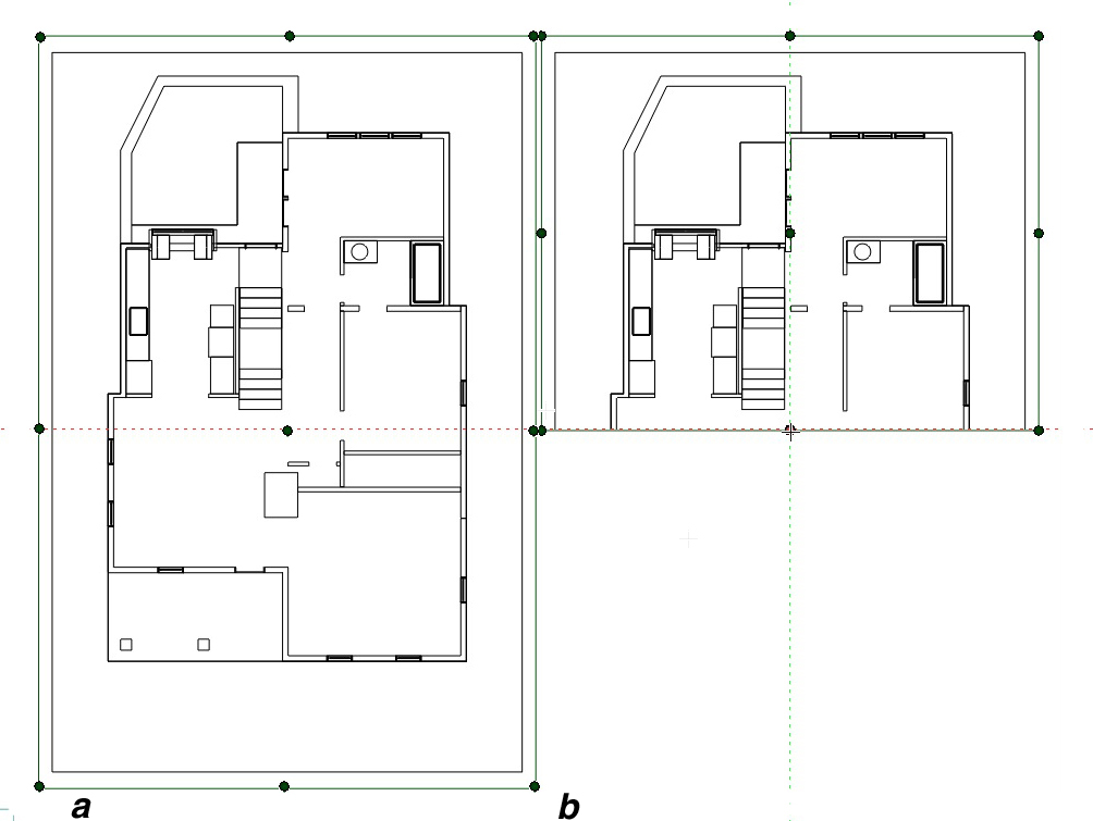
A frame being edited with it's controls (a)uncropped, and (b) cropped.
Pressing the command key (Macintosh) or ctrl key (Windows), changes the editing from cropping to re-centering the display in the frame of the image in the corresponding direction. Pressing the shift key keeps the changes proportional to the current size of the image.
 Place Multi-Frame
This tool creates a layout of multiple frames at once. This is like using the Frame tool multiple times. It automatically creates multiple frames from the same model file in a single step. A rectangle representing the location and size of the multiple frames is drawn first, with two mouse clicks. Next the Multiple Frame Parameters dialog is invoked for the selection of the layout of the frames and 3D model and other parameters for each frame in the layout.
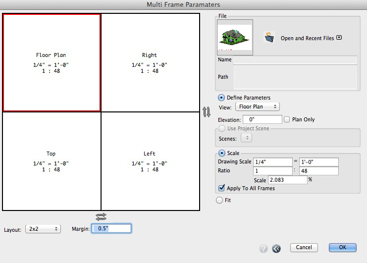
The Multi-Frame Parameters Dialog.
The left side of the dialog contains a graphic preview of how the frames will be divided and sized and indications of the view and scale for each frame. Clicking inside a frame highlights it making it the active frame and its parameters are shown in the options to the right.
There are two Flip buttons (![]() ) on the right and bottom of the frame. The one on the right flips the frame layout vertically. The one on the bottom flips the frames horizontally.
) on the right and bottom of the frame. The one on the right flips the frame layout vertically. The one on the bottom flips the frames horizontally.
The Layout menu contains a list of the available configurations named by the number of frames horizontally and the number of frames vertically.
Margin: This parameter represents the space left between the frames.
Most of the parameters on the right are the same as those found in the Frame Parameters dialog. The Layers and Clipping Planes are initially unavailable, but they become available and can be modified by editing the frames after they have been created.
The file that is selected is used for all of the frames. The rest of the parameters reflect the values for the active frame on the left side. The Apply To All Frames option applies the selected scale to all frames that are placed by scale. This option makes it easy to have the same scale for all frames. This is on by default.
Once the layout and the parameters are set to the desired values, click OK to create the frames in the previously drawn rectangle.
 Place Image
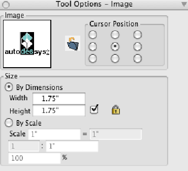
The Place Image tool options.
This tool is used for placing an image from an external file into the drawing. This is useful for placing a rendered image or any graphic elements like logos etc. The image and its size are displayed in the Tool Options palette. The image can be selected by clicking on the Open icon (![]() ) and then selecting the desired image file from the File Open dialog.
) and then selecting the desired image file from the File Open dialog.
As soon as you activate the Place Image tool, an image appears at the position of the cursor and moves as the cursor moves. The alignment of the image with the cursor is determined by the Cursor Position option selected in the Tool Options palette. The nine radio buttons represent the corresponding location on the image boarder and center respectively. Clicking places the image at the location of the mouse click.
The size of the image is controlled by the By Dimensions or By Scale options. With the former option the size of the image in the drawing is specified. With the latter option, the scale factor is specified. This is useful when an image is provided with specific scale information that is important for the drawing.
Once created, an image object behaves as a regular object; it can be moved, rotated, scaled, copied, deleted, etc.
Once placed, image objects can be graphically edited by enabling the controls on the object in the standard manner. Image objects have nine controls that represent the corresponding image corners, image edges and image center. Moving the center control moves the entire image. Moving the corners and edges changes the cropping (clipping) of the image, keeping the scale of the image consistent. Pressing the command key (Macintosh) or ctrl key (Windows), changes the editing from cropping to stretching of the image in the corresponding direction. Pressing the shift key keeps the changes proportional to the current size of the image.
Image objects retain the link to the original image file. When the image file is changed, the linked file is reloaded in the project to display the updated image. The image file link can be managed through the linked files section of the Project Information dialog, accessible from the Help menu.
 Place Image Fit
This tool also creates image objects from an external file. With this tool the image is fit into a rectangle. The image and its size are displayed in the tool’s options palette. The image can be selected by clicking on the Open icon (![]() ) and then selecting the desired image file from the File Open dialog.
) and then selecting the desired image file from the File Open dialog.
To place the image, the first click defines one corner of the image. As the mouse is moved, the image is stretched as it follows the cursor. A second click completes the operation.
Layout palettes
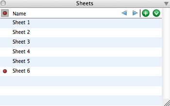
The Sheets palette.
The Sheets palette is used to manage the sheets in the project. This is a standard list palette that lists the sheets in the project by name. One sheet in the project is referred to as the active sheet. The active sheet is indicated by a red dot in the first column of the palette (to the left of the sheet name). Clicking in this column makes the corresponding sheet the active sheet. The graphics window is updated so that the active sheet fills the window.
A new sheet is created by clicking on the Add ( ) icon at the top of the palette or by selecting New Sheet from the palette's menu. When a new sheet is created, it is placed at the end of the list and automatically becomes the active sheet. Sheets can be reordered by dragging the sheet name to the desired location in the list using the standard click and drag method. Clicking on the
 ![]() (previous sheet) and
(previous sheet) and ![]() (next sheet) icons at the top of the palette changes the active sheet to the previous or next sheet respectively.
(next sheet) icons at the top of the palette changes the active sheet to the previous or next sheet respectively.
Double clicking on a sheet name invokes the Sheet Parameters dialog that can be used to change the name of the sheet. This dialog also offers options to suppress the border and the title block for the sheet. These can be desirable, for example, when making a cover page where the boarder and title block may not be desired.
Sheets can be deleted by right clicking on the sheet and selecting Delete from the context menu. Note that, when a sheet is deleted, the contents of the sheet are deleted as well.
In addition to the other standard management items, the context menu also contains the item New Multi Frame Sheet. This creates a new sheet and fills it with multiple frames. This functions the same as the Multi Frame tool, except that the frame fills the sheet instead of a drawn rectangle.
Layout Printing
The print command invokes the Plot/Print Setup dialog where print parameters are set and the sheets of the document can be sent to a printer, plotter or PDF file. The left portion of the dialog contains a preview of a sheet to be printed. The sheet text field and previous and next sheet arrows at the bottom of the preview control the sheet that is shown in the preview.
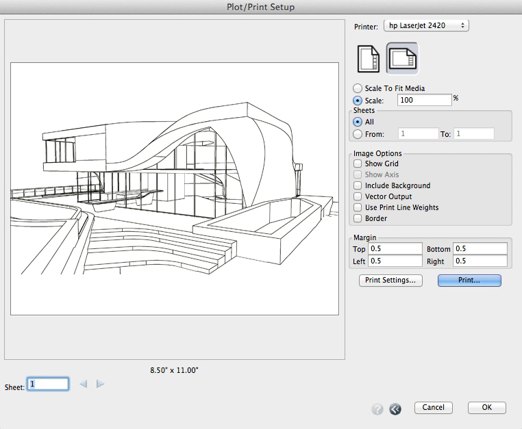
The Plot/Print Setup dialog.
The right side of the dialog contains options for controlling the printing.
Printer: This menu contains the list of printers that are available on the computer. The printer selected from the menu is the active printer and the destination for printing.
Orientation: The icons control the orientation of the page Portrait or Landscape.
Scale to Fit Media: When selected the sheet is scaled to fit on the page.
Scale: When selected the sheet is scaled to the specified scale. If the scale causes the sheet to exceed the size of a single page, it will be printed on multiple pages. In this case the preview shows lines on the sheet to indicate how the sheet will be split into multiple pages.
Sheets: This section controls what sheets will be printed. All prints all sheets in the project. The From and To options control the range of sheets to print.
Image Options: This section controls addtional printing options.
Show Grid: This option controls whether the reference grid will be included in the print. Note that whether or not the grid is printed is independent from whether it is currently displayed in the window.
Show Axes: This option controls whether the axes will be included in the print. Note that whether or not the axes are printed is independent from whether they are currently displayed in the window.
Include Background: When this option is selected, the background of the plotted/printed image is filled with the background color. This option is most useful when using color printers. It is off by default.
Vector Output is an option for Layout projects in wireframe or hidden line display. With this option the line work and text are printed as resolution independent geometry to printers and PDF files.
Use Print Line Weights is an option for printing with the line weights you have specified in your project file.
Margin: Defines the border around the physical edge of the paper in which nothing is printed. The margin setting can be used to limit the printing for aesthetic reasons but also it is important to note that most printers cannot print to the edge of the paper so you should select a margin that reflects the printer's characteristics. This is the same parameter available for the layout and is provided here as well for convenience.
Print Settings: This button invokes the system specific print settings dialog where a number of printer specific parameters can be set. If the printer supports different paper sizes, the desired paper is selected in this dialog.
Print: This button invokes the system specific print interface to send the document to the printer or PDF file.
Components
Components can be placed in a layout using the Place Component tool as with the modeling environment. A common use of components is to add detail or information to a drawing (e.g. fixtures, furniture, etc.) from a library of commonly used parts. When a component is placed into a frame in a drawing, it is automatically scaled to the frame’s scale. This avoids the necessity of creating components for each desired drawing scale or changing the component when the drawing scale is changed.
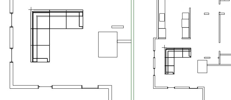
A couch component placed in two frames with different scales.
It is also useful to have components for graphic symbols that are designed to be placed on a sheet such as a North arrow, electrical symbols, etc. These are components that are created at layout paper scale (i.e. 1:1). These components are not scaled by a frame scale regardless of where they are placed in the drawing. Layout components are listed in the components palette in the Layout tab. When the layout tab is selected, the palette displays a set of component libraries for layout placement. Layout components are stored in .fml file in the components’ library folder on disk.
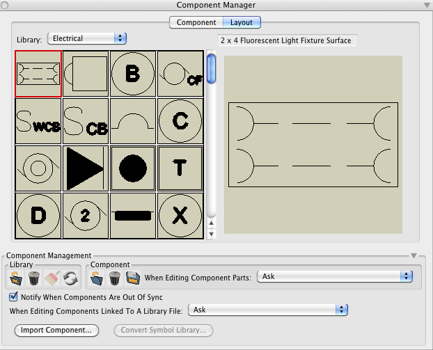
The Layout tab of the Component Manager palette.
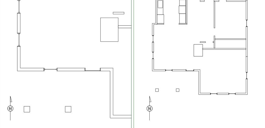
A North arrow placed from a Layout library placed in two frames with different scales.
form•Z draft files from versions prior to 7
Traditional form•Z draft files created with versions prior to version 7 are converted into form•Z 7 files (.fmz). The original drafting elements are converted into form•Z objects. Drafting panes are converted into frames. Drafting Layouts from previous versions are not currently transferred.