Reference planes
Graphic interaction with form•Z is interpreted relative to the active reference plane. A reference plane is a plane in 3D space used as the workspace for drawing and the basis for other interactive actions. The initial reference plane is the XY plane (or ground plane). The reference plane may be one of the three Cartesian planes (XY, YZ, ZX), or it may be a custom plane. A custom plane can be positioned anywhere in 3D space and is defined from faces of an object or is derived from one of the Cartesian reference planes. A special type of custom plane is the face reference plane, which is created automatically when using a tool for drawing objects and the mouse is positioned on a face of an existing object.
By default, reference planes are shown with a grid and axes. The X axis is displayed red, the Y green, and the Z blue. The color of the grid and axes is controlled by settings in the Appearance tab of the Project Settings dialog (accessed from the File menu). The display of the grid and axes can be disabled with tools in the Display tool palette.
The Reference Plane tool palette is located at the bottom left edge of the screen. It contains tools that can be used to switch between the reference planes, define and edit planes.
![]() XY Plane,
XY Plane, ![]() YZ Plane,
YZ Plane, ![]() ZX Plane: Make the XY, YZ, or ZX reference plane active, respectively.
ZX Plane: Make the XY, YZ, or ZX reference plane active, respectively.
The Reference Plane Parameters palette that can be invoked from the Palettes menu, contains the parameters of the current plane. This includes a control for the plane’s underlay. The underlay is an image that can be displayed on the plane. This is useful for referencing or tracing images.
![]() Custom Plane: Makes active the custom reference plane that is active in the Custom Reference Planes palette. This palette can be invoked from the Palettes menu and contains a list of all the custom planes that have been defined. It can be used to manage the custom planes, including the selection of the active custom plane.
Custom Plane: Makes active the custom reference plane that is active in the Custom Reference Planes palette. This palette can be invoked from the Palettes menu and contains a list of all the custom planes that have been defined. It can be used to manage the custom planes, including the selection of the active custom plane.
![]() Module and Divisions: A grid may be drawn depicting the reference plane, depending on whether Show Grid is selected in the Display menu. The density of the grid is specified by the values in these two fields. The module value specifies the interval at which a heavy line is drawn. The divisions value specifies the number of subdivisions in each module. These subdivisions are drawn in lighter lines.
Module and Divisions: A grid may be drawn depicting the reference plane, depending on whether Show Grid is selected in the Display menu. The density of the grid is specified by the values in these two fields. The module value specifies the interval at which a heavy line is drawn. The divisions value specifies the number of subdivisions in each module. These subdivisions are drawn in lighter lines.
![]() Define Reference Plane: This tool allows you to define custom reference planes from faces of objects. To do so, with the tool selected, click on the face of an object.
Define Reference Plane: This tool allows you to define custom reference planes from faces of objects. To do so, with the tool selected, click on the face of an object.
![]()
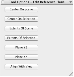
The Edit Reference Plane Tool Options Palette
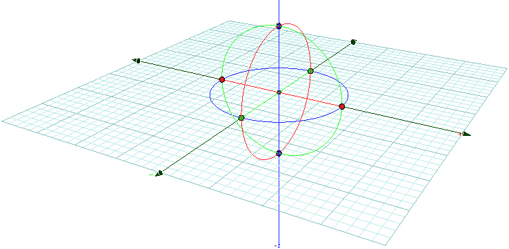
The XY reference plane grid with its
controls displayed.
Edit Reference Plane:This tool allows you to manipulate a reference plane grid and to derive a custom plane from it. There are seven buttons in its tool options palette:
Center On Scene changes the origin of the plane to the center of the scene extents. Center On Selection changes the origin to the center of the selected entities. Extents Of Scene changes the extents of the plane to the scene extents. Extents Of Selection changes the extents of the plane to the extents of the selected entities. Plane YZ and Plane XZ change the plane to the YZ or XZ plane of the current reference plane. Align With View changes the plane to coincide with the picture plane of the current view, with Z aligned to the line of sight, X to the horizontal and Y to the vertical axes of the screen.
Activation of this tool also displays controls on the reference plane grid, which can be used to graphically reshape the plane. By picking and dragging the border arrows that appear on the four border lines you can expand or shrink the respective side of the reference grid. By rotating the circular dials that are centered at the origin of the plane you can rotate the plane grid in three directions. You can also move the grid by moving the bullet at its origin.
![]() Lock Reference Plane: This is a switch. When this switch is on, the reference plane is locked and does not automatically change when using one of the drawing tools. When this switch is off and you place the mouse cursor on the surface of an object, while a drawing tool is active, drawing will occur on the surface of the object. This tool can also be accessed by its key shortcut (F5) which is useful when the mouse is positioned on a face of an object and the icon cannot be used.
Lock Reference Plane: This is a switch. When this switch is on, the reference plane is locked and does not automatically change when using one of the drawing tools. When this switch is off and you place the mouse cursor on the surface of an object, while a drawing tool is active, drawing will occur on the surface of the object. This tool can also be accessed by its key shortcut (F5) which is useful when the mouse is positioned on a face of an object and the icon cannot be used.