Animation Deformation Tools
Animation Deformations reshape an object or group of objects over time based on a deformation method. Animation Deformations share the same methods found in the Reshape modeling deformation tools, such as Bulge, Twist, etc. The notable difference between modeling deformations and animation deformations is that the deformation information is retained in an animation node. This allows for the deformation parameters to be animated and for multiple objects to share the same deformations. Animation deformations are a process that are applied in the animation evaluation and do not make permanent changes to the original object. That is, the original object's parameters are retained but the object appears deformed. This enables the animation of the object’s parameters and a deformation simultaneously. For example, an extruded object can simultaneously have its height animated and have an animated twist applied.
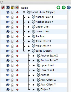
The Animation Score palette with bulge
object and bulge cage deformation groups.
Animation Deformations appear as groups in the Animation Editor palette as with other animated entities (objects, lights, groups etc.). Objects that are placed in a deformation group are deformed by its deformation parameters. Objects can be added to a deformation group through the Animation Deformation tools or by dragging the object into a deformation group in the list side of the Animation Editor. The parameters that control the deformations vary, depending on the deformation method. The parameters are represented by corresponding tracks for each parameter.
Most deformations are based on a reference plane referred to as the base plane and an axis which is usually the line perpendicular to the base plane, through the origin of the plane.
An Animation Deformation can be applied to the objects in the deformation group individually or collectively. When applied individually, the deformation parameters are applied to each object using the object’s coordinate system defined by its axes. That is, the X and Y directions of the local axis define the deformation base plane and the Z axis is the deformation axis.
When applied collectively, the base plane and axis for the deformation are defined explicitly in the deformation group. This is referred to as the deformation cage. The cage is defined when a deformation group is created. The parameters of the cage can be edited and animated. The explicit definition of the deformation cage makes this method useful even when applied to a single object, as it gives much more control over the deformation and allows effects that can not be created with the implicit method. This type of group is referred to as a deformation cage group.
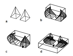
Once created, deformation groups can be placed inside of each other to create nested deformations. Deformations can be re-grouped in the standard fashion by dragging a deformation in or out of another deformation group in the animation score palette. This allows for an object to be simultaneously animated with multiple deformations. The figures below show examples of nested Taper and Bulge deformations.
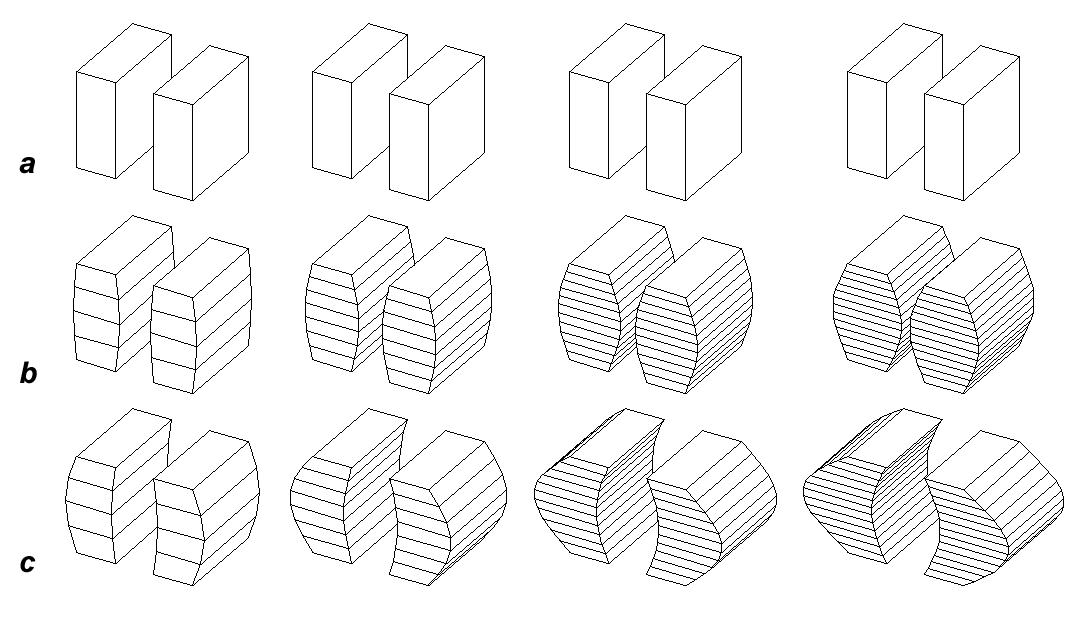
Animated bulge deformation applied to two extruded objects using (a) a deformation
object group and (b) a deformation cage group.
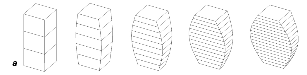

Simultaneous taper and bulge deformations applied to an object: (a) Stages of the animation with the
Bulge Anchor Scale X track increasing in value and the Taper Lower Scale Y track decreasing in
value. (b) The Animation Editor showing the Taper nested inside the Bulge.


 Animated Deform Tools
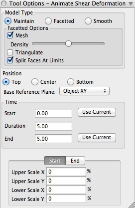
The Animate Shear tool options palette.
These tools automatically create a deformation group in the animation score. The type of deformation is determined by the tool picked, and the options for each is controlled in the Tool Options palette for that tool. The Animate Shear tool options palette is shown at right.
This tool may be applied in either prepick or postpick mode. In postpick mode, with the tool active, click on an object. The deformation group is added to the animation score and the selected object is placed into the deformation group. You can also click anywhere in the modeling window that does not contain a selectable object. This will create the deformation group without any objects in it.
When using the prepick mode, all of the multiple objects can be added to the deformation group. The multiple desired objects are selected first using the Pick tool, then, with the Animation Deformation tool active, click in the modeling window. The deformation group is created and all of the prepicked objects are added to the group.
Model Type: This group determines the type of model that is created from the deformation operation. Both facetted and smooth objects can be deformed and each type will result in different effects.
Maintain: When this option is selected, the result object will be the same type as the original object's type. This is the default.
Facetted: When this option is on and a smooth object is picked, the smooth object will be converted to a facetted object. It is often useful to use this option for explorations, until the desired results are achieved, before switching to the Smooth option, which is computationally more intensive.
Smooth: When this option is on and a facetted object is picked, the object will be converted to a smooth object. This does not work well when the original object has a dense mesh, because smooth deformations are computationally intensive and work best on objects with lower face
Facetted Options: This group applies when facetted objects are deformed. Note that there are no analogous options for smooth objects.
Mesh: This checkbox determines whether or not the object will have a mesh created for it as it is being deformed. If this box is checked, meshing takes place and then its density can be controlled by the slider below. The farther to the right the slider is moved, the higher the density of the mesh will be. The resulting animation will show smoother surfaces during the deform.
Triangulate: When this option is on, the non-planar faces of facetted objects are triangulated.
Split Faces At Limits: When this option is selected, the faces of the source object are split along a new edge that corresponds to the limits of the deformation. This is option is necessary when deforming an object with only a few large faces. If the source object is of sufficient density of faces, this option may be disabled and the source object will retain the same number of faces after the operation. It is often desirable to use this option when animating deformations as the original objects topology is preserved. This option is on by default.
Position: This determines where the active deformation is located. As in deforming an object normally (not animating), the control for graphically setting the deform parameter value would be appear in this location. In the case of animation, it is simply used by the tool when it applies the deformation.
Base Reference Plane: This option allows you to specify the reference plane that will be used as the base plane for the deformation. Note that if the Object (XY), Object (YX), or Object(XZ) options are selected and no objects are picked, then the XY, YZ, or ZX options are used instead.
Create Object Group: When this option is selected, the deformation group is created as an object group. That is, the deformation is applied to the objects in the deformation group individually as described above.
Create Cage Group: When this option is selected, the deformation group is created as a cage group. That is, the deformation is applied collectively to all the objects in the deformation group using a common axis. If no objects are selected, the origin for the cage is the click point. The extents of the cage are determined by the Min and Max values in X, Y and Z, as specified in this group.
Extents From Selected Objects: When this option is enabled, the combined extents (bounding box) of all of the selected objects is used as the cage. When this option is off or there are no objects selected, the above Min and Max parameters are used.
Origin From Selected Objects: When this option is enabled, the origin of the deformation group is established from the average of the origins of the selected objects. When this option is off, or no objects are selected, the origin point is the click point.
Add All Tracks: When selected, all available tracks for the active deformation method are added to the new deformation group.
User Selected Tracks: When this option is selected, the Add Tracks dialog is presented for the user to select which tracks of the deformation should be added. The tracks listed in the dialog will vary depending on the deformation method being used.
 |
 |
|---|
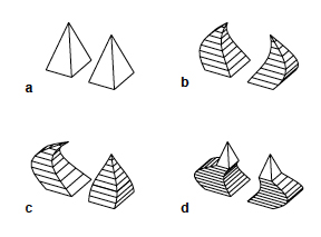
Deformation Cage Group Examples: (a) original pyramids, (b) Extents From Objects on and Origin From Objects on, (c) Extents From Objects on and click point (d) Extents From Objects off and click point.
The Query Deformation Group dialog
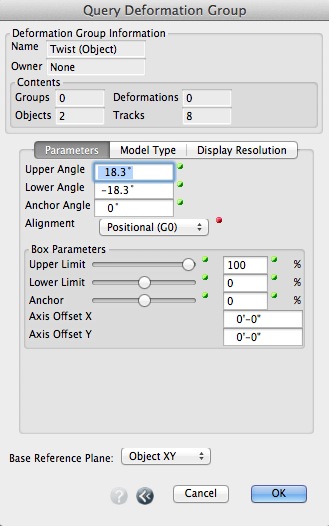
The Query Deformation Group Parameters tab.
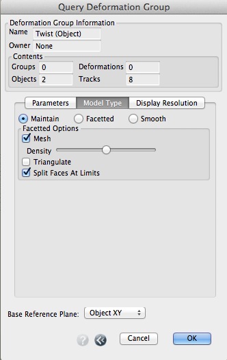
The Query Deformation Group Model Type tab.
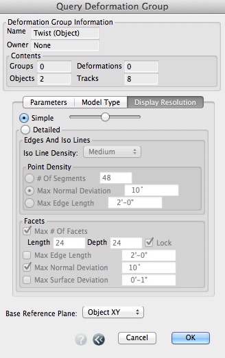
The Query Deformation Group Display Resolution tab.
This dialog provides information about a deformation group and access to the group's parameters. This dialog is accessed by double clicking on a deformation in the Animation Score palette, or by selecting the Controller Options... item from the Score palette's contextual menu, or from the Options... button in the Animation Manager dialog.
Deformation Group Information: This section of the dialog contains information about the deformation group.
Name: The name of the deformation group. The name can not be changed. The name is the name of the deformation method followed by either (Object) or (Cage) to distinguish the two types of deformation groups.
Parent/Owner: This is the name of the group in which the group being queried resides. If it is not in a group, then this field will read None.
Contents: This group contains statistical information about the contents of the deformation group including the number of Groups, Objects, Deformations, and Tracks.
Parameters: This tab displays the parameters of the deformation. The contents of this area varies depending on the type of the active deformation, as each deformation has its own specific parameters. Most of the parameters can be edited relative to the deformation box (percentage) or in their real world dimensional coordinates. These parameters have a slider with a percentage text field to the right, followed by a numeric text field. The slider and text fields are all linked to the same parameter. This allows the percentage slider to be used when the actual dimension is less important and experimentation is desired. The dimensional text field can be used when accuracy is desired.
Group And Box: This tab is only available for deformation cage groups. It contains items that define the group transformation and box for the cage deformation. The contents of this tab are the same for all deformation types.
Group Transformation: This sections defines the axis used to define the coordinate system or reference plane for the deformation. These values are initially derived from the Base Reference Plane option in the Animate Deformation Options dialog.
Box: This group contains the parameters for the deformation cage. The deformation box is defined by the Min and Max values in X, Y and Z dimensions. These values are relative to the coordinate system (reference plane) defined by the above Group Transformation.
Base Reference Plane: This menu is only available for object groups. It displays the reference plane used for the object deformation.
Model Type: This tab displays the resultant geometry type that will be used for the deformation.
Display Resolution: This tab displays the standard display parameters for smooth objects. The values in this tab are only used for smooth objects.
