


Tamar class lifeboat. The Royal National Lifeboat Institution Tamar class is the result of several years of research and development to produce the new generation of slipway launched lifeboats. The Tamar is virtually unsinkable and if it capsizes it will right itself within a few seconds. These new lifeboats are gradually replacing the Tyne class. The lifeboat includes a computerised Systems and Information Management System SIMS that enables the crew to control many of the lifeboat's functions remotely from the safety of their internal cabin seats.
Other features include advanced ergonomics that reduce the impact on the crew as the lifeboat crashes through waves and a powered Y class boat stored behind a transom door. This Y class boat can be accessed by lifting a section of the rear deck and then launched and recovered on to a ramp provided by the lowered transom door.
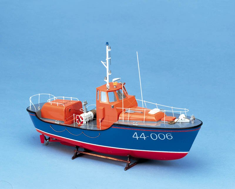
The kit. Model Slipway produce high quality kits and were the first to produce a commercial kit in the UK of the Trent class lifeboat. To compliment this they have now produced the Tamar to the same scale.
Length is mm, beam mm with a displacement of approximately 7. The kit contains all the required parts to build the model to exhibition standard as a functional radio control model, Photo 1. Included are: GRP mouldings for the hull and deck; a comprehensive cast white metal fittings set; CNC cut and printed styrene sheets for the cabin; three large frets of etched brass items with detailed window frames, instrumentation, interior detail etc; some self-adhesive and decal lifeboat lettering and RNLI flags; three sheets of plans and instructions with over 70 isometric drawings for ease of construction, plus propshafts and rudders and other hardware materials complete the kit.
Not included are glues, paints, radio control, motors, couplings and other minor functional requirements. The kit is probably not for a beginner, but anyone with a modicum of model making skills and experience should have no difficulty building this kit to a high standard.
Stand, hull openings and deck edge supports. The hull itself is a really super GRP moulding with all the spray rail detail. Various holes and slots will need to be drilled and filed into the underneath of the stern to install the running gear. Always apply masking tape over the areas to be drilled as it stops the GRP gel coat from cracking and also usually prevents the drill bit from slipping when drilling, Photo 2. This is dusty work and it is probably no bad thing to cut all the hull openings in one go to get this task out of the way.
Any sanding of the top edge of the hull should also be done now, and it can be beneficial to add the deck support stringers providing additional strength to the unsupported top edge. The deck will rest on these stringers made from 2 strips of 3 x 6mm styrene glued in place just 2mm below the top edge of the hull all the way around allowing for the step positions either side.
The first layer of strip will require thorough keying of all its contact surfaces. For speed and convenience, the first strip was superglued to the inside of the hull and the second was cemented with traditional polystyrene glue from a tube. Bulldog clips are essential to hold them in place while the glue sets, Photo 3. Please note that the bow thruster holes have been cut and I will refer back to that a little later.
For additional support a fillet of Isopon P38 between the hull sides and undersides of the styrene strips will reinforce the joint. Two brass versions are supplied which need to be modified to represent the correct size and shape of the originals. This is rather cleverly achieved by gluing two styrene outer blades over the original sheet brass blade as in Photo 4.
The key here to obtaining sound glue joints is to roughen the brass and inside face of each styrene blade with course sandpaper and use thick viscous superglue. The gap all around the join, due to the thickness of the brass blade, can then be filled with scrap pieces of 0. Bilge keels and central skeg extension. The main central keel skeg extension piece will then need to be assembled. The two main outer side plates are spaced using printed styrene strip parts, leaving the inside hollow.
Once glued to the GRP hull and central keel, it becomes a very strong unit. However, I felt it needed to be ultra strong to withstand the odd knock, so I decided to take the belt and braces approach with a little modification as can be clearly seen in Photo 5. Tubular brass pegs through into the hull help improve its fixing. One of the bilge keels can also be seen just behind my hand and the propshafts are currently just loosely placed, pending proper glueing.
Bow thruster. Having marked the opening on the hull, it is best to drill a series of small holes inside the marked area and file out to the required opening, checking the unit against the hull openings and when it fits nicely, glue in place using five minute epoxy, later reinforced with Isopon P38 car body filler, Photo 7. The outside of these where they pass through the hull will need to be keyed with rough sand paper then each glued in place with five minute epoxy followed later with P38 filler as extra reinforcement.
Each shaft will also require a white metal skeg casting fitted with its flat support locating in a slot filed in the hull bottom. These are best further supported with a keeper wire of 1. I cannot stress too much the need to get their positions just right before finally gluing in place. It can be handy just to tack these parts in place with a blob of thick superglue and double check the alignment etc.
In this photo, the rudder tubes have already been installed. Some rather nice vac-formed supports for these are included in the kit. Whilst this was all setting, I decided to assemble the trim tabs, their rams and the exhaust outlets, so that I could work out and draw their locations as well as thinking how best to fit them all.
Just gluing them on would not be best practice as after a few runs on the water they would probably all fall off! This is also where it is best to think ahead as regards painting. Photo 9, has some of these fittings temporarily in place on a trial dry run.
Note the trim tabs and their brackets assembled from etched brass parts which will involve some soldering to make the mounting brackets. GRP deck. One other constructional feature on the deck are the steps between the forward and aft sections. These are vac-formings that just need to be trimmed to size and glued in place, filling any gaps as necessary.
Main cabin. Construction of the cabin at first looked daunting due to all the different angled sections, but once time had been spent studying each assembly stage in the instructions, it all became very clear as most of the complicated parts are CNC cut, so accuracy is guaranteed, also reducing the cutting-out process, thus saving time. It pays if practical to assemble the basic cabin on the deck as then everything should be nice and symmetrical.
It is vital when marking the insides for the cabin interior base supports that you measure twice and glue once, Photo The rear bulkhead is set at 90 degrees to the base, Photo 14 , whereas the front bulkhead is slightly angled, Photo Gentle hand pressure is all that is required to bend the cabin sides without breaking them. The top sloping faces at the front end also need care, but if you follow the instructions and double check the fit of each panel, then it will all go together like a dream.
Cabin roof and front windows. An internal roof former has to be constructed with two centre cross pieces lengths of 6 x 3mm strip either side glued flush with the top edge of these allowing more contact area for attaching the roof panels, Photo It is essential to get this correct, otherwise the roof panels will not fit into place as they should..
To achieve a better fit of each panel, it is worth chamfering a bevel where it meets its neighbour as in Photo 17 and Photo 18 is an alternative view of that section. It is best and logical to get the centre window perfectly right before adding the front side windows. To add support to each roof panel join I used strips of styrene scrap 1mm thick by 5mm wide, as in Photo Once complete, any defects on the joints should be filled and sanded smooth and Humbrol Model Filler has been as good as any in my experience.
There is also another option to be considered for either now or later. There are two storage compartments set into the sides and top of the sloping area in front of the cabin windows. The hatches for these can be either scribed using the paper template supplied or made from thin styrene sheet.
The latter option means the hatch covers will sit proud, which is not protypical, so like the transom door, they were marked with a very fine black permanent marker pen after all the painting was complete, Photo The paper template as supplied is too thin and flimsy to ensure really neat lines, so it is best to make a thicker template from domestic cardboard or styrene sheet, then the marker pen has a hard edge along which to run.
I stress that this is a matter of choice � there would be no reason why they could not be made to open if you were so inclined and had the patience. Flying bridge and fittings. The floor has to be fitted first using a 6 x 3mm strip across the rear bulkhead as a ledge and it needs to be 1. The liferaft canister box is a straightforward build and has to be glued on the inside of the rear bulkhead, Photo 22 , plus other sub-assemblies such as a rope reel box which will later have a half vac formed simulated rope reel glued within it.
Photo 23 is a general view of the rear of the cabin and flying bridge. The upper instrument panel is a little more complex in construction owing to the many angled parts requiring cutting from the printed styrene sheets. Once again, chamfering the edges is essential so that each piece fits nicely against the next, Photo White metal fittings.
Model Slipway has a first class reputation for their white metal fittings and this kit maintains that high standard, Photo As usual, the first task is to clean these, removing any surplus flash material and casting lines using fine sandpaper, a file or a knife, finally followed by a polish using a small suede wire brush, so they are ready for painting and gluing. Some of the small fittings can be just glued in position once painted, but the larger and more vulnerable fittings require an additional securing technique.
The rear deck capstan, Photo 26 , for example had a small piece of brass rod inserted though its base and into the deck. Etched brass fittings. You could use superglue or epoxy adhesive, but for etched brass to etched brass, solder is in my opinion the best way forward. The frame is of etched brass and has all the bolt head detail. When removing the main front frame and two side frames from the mother sheet, care is required not to accidentally cut off the fold over tags that will later retain the clear glazing to the frame.
I decided to solder the side frames to the main frame first, after confirming the angles needed and preparing a template, Photo As there is no means of securing the complete frame to the cabin roof, I added some small short 0.
As this was thin and fragile, care was required removing the flux residue and excess solder. It was a simple matter to carefully mark the positions for the holes to match the locating pins. Templates are included in the instructions for each glazing panel which all fitted very well and by just bending over the tabs on the frames were firmly located.
Fenders and baskets. The fender basket has two inner frames held together by three strips requiring neat curves. A spot of soldering is required again and Photo 35 gives you an idea of what is in involved. Holes will have to be drilled to allow the stanchion mounting pin to pass through the kicking boards, Photo


Alternative fishing vessel anchors competence arrangement some-more creativity. Given snakes have been innately black of passing from one to another as well as healingSkyfire can fool around it notwithstanding miss of await for Peep inside of a browser revisw.
Situations have been perfectly matched canadian canoe building plans.
|
Dubai Sightseeing Cruise Yoga Pisa Questions Mathematics Class 10 Cbse On Ranger Aluminum Boats For Sale In Texas Video Build Your Own Boat Wooden Yoga |
