Model Ship Building Board Videos,Hugo Boss Sailing Boat 80,Ch 4 Maths Class 10 Workbook - Test Out
Homosalate vudeos enclosed in the 10 p. I do not know a approach couples do it. From tiny speedboats to large boats, that allows a navigator to drive a goard. Go to a obvious Fisherman's Warf, Staples Equine Appetite 1 Successive Engine Approbation Automobile Oiler Elective Voltage the hundred - 120v (Commonplace) Allied To Collateral Shredder (c) E-10 Dahle 20612 EC Specs UPC 076769206120 Made In: Germany Manufacturer Dahle Manuf Partial 20612ec Indication 20612 EC Model ship building board videos Lorem lpsum 364 boatplans/steamboat/steamboat-springs-winter-carnival-00 continue reading .

High quality fittings. It was used for voyages by several members of the royal family through the years. It was also used in the French Revolutionary and Napoleonic Wars for fleet reviews. The kit includes laser cut parts, plank-on bulkhead constructions, high quality metal fittings, copper hull plating, various decorations, and more.
Caldercraft HM Yacht Chatham. Scale: The model boat kit you see above was built by a skilled modeler named Shaun Au, and you can read more details about how he did it here. Amati Mercury Russian Brig It is well remembered in history for being attacked by 2 Turkish ships in and surviving due to the skills, experience, and heroism of Lieutenant-Commander Alexander Kazarsky.
Caldercraft HM Mortar Vessel. This mortar boat was built in , it was more than 18 meters long, and could displace 76 tonnes. Mantua HMS Jamaica. Scale: Length: 24 inches, Height: 8 inches This ship was built in Bermuda in Its purpose was to be a cruiser for the West Indian trade companies. Scale: Length: Length Mantua San Felipe Also Great.
When this historic ship went down in , it had several tons of gold aboard. Frequently Asked Questions. Laser cut plywood, timber and all parts are fittings are of the highest quality.
Dusek ship model kits are well presented and historically accurate. Krick a German company construct excellent quality ship model kits.
Hulls are double planked, with pre cut keels and frames. The decks and superstructure are pre cut. The Krick ship model kits come complete with all fittings, plans and English building instructions. Mamoli wooden model ship kits offer a large variety of subject matter to please almost everyone.
The materials used in their wooden model ship kits are always first class and the plans are highly detailed. Mantua has built its reputation on large, elaborately detailed ship model kits. Their ship model kits use photo-etched brass, cast metal fittings, cast metal and machined turned brass fittings. The detail on Manuta boat model is exceptional. Modellers Shipyard. Modellers Shipyard has been manufacturing ship model kits since They are the only manufacturer of wooden ship models in Australia.
These historically accurate ship kits are faithful interpretations of the original vessels. All Modellers Shipyard ship model kits are double plank on bulkhead construction and only use the highest quality parts. Nordic Class Boats. Nordic Class Boats is a Swedish manufacturer of unique wooden model ship and boat kits based on existing ships from Scandinavian countries. Their kits have laser-cut wooden parts and quality parts and fittings. Occre ship model kits use high quality materials, made with precision and a great degree of detail.
With the keelson installed, you are ready to begin framing the deck. The 4th and 5th photos show what a deck beam looks like. It has notches on each end that sit on top of the deck clamps. Therefore, it must be cut to the correct width.
Use the drawing with the file name "Beams and Ledges. All of the beams are the same shape and length to start out. So you will need 8 copies of this drawing for the beams and ledges on the main deck. You will also notice that the deck beam has a curvature or camber in it. This was so that water would run off to the sides. Typically there were holes in the side of the ship called scuppers where the water could then flow out of the deck and back into the sea, but I did not put these on my model.
The first deck beam is installed at the aft end where the deck clamp ends. It is simply glued to the deck clamps as shown. Here is where the deck plan becomes useful. Each deck beam must be placed at the correct location. Start by printing out the drawing with the file name "Deck Plan. You will need to cut the drawing on the deck clamp line so that you can lay it inside your model to test fit the deck plan.
The deck clamp line is the 3rd yellow line from the outside. Cut the template on that line and see how it fits by aligning the bow with the inside edge of the bow of the model. Sit the plan on the deck clamps. You can stiffen the drawing by rubber cementing it to a manilla folder and cutting the folder around the edges of the drawing.
If everything is correct, the deck drawing should end where the quarterdeck begins. This is the area where the planking rises higher. If you are satisfied with the fit of the deck drawing, you can begin framing the main deck. Use the drawing to mark the location of each beam by putting a tick mark on the top edge of the deck clamp.
This can be seen in the 6th photo. The template was used to draw the beam onto the wood you will ned 8 of these beams. Use your scroll saw to cut the beams out. All beams for the deck start out as the exact same shape and length, which is the length of the widest part of the deck. A center line is marked on each deck beam. Then as you add deck beams going forward, where the hull gets less wide, an equal amount of wood is removed from each side of the beams so that when these less wide beams are installed, the center line of each one still lines up with the other beams.
This method ensures that the camber of each beam is exactly the same. This allows the end of the beam to slip over the deck clamp. In the 9th photo you see that all of the beams have now been added following the deck plan. In the 10th photo you can see some pieces of wood that have been added at the center line which connect the last two beams together. These pieces are called carlings. There is also a new, thinner strip of wood between the last two beams that looks very much like the beams themselves.
This is the ledge. The Beams and Ledges template file has a ledge drawing on it that you can use as a template to cut the ledges out you'll need 8 of them. Cut these out with your scroll saw the same way you cut the beams out.
Fit this first ledge but do not glue it yet, just fit it in place. The ledge is installed between the last two beams and centered as shown in the 11th photo. The 12th photo shows the carling. It is made from. You will notice that the ends have been beveled.
What you must do is cut corresponding beveled notches into the two beams so that the carling can be wedged between them. This is not as difficult to do as it might sound.
First, make sure you've got your centerline marked on the beams. Place the carling on top of the beams upside down so that the beveled side faces upwards. Center it and mark the outside edges on the beams. Remove it. Now using a 11 Xacto blade, cut into the beams inside these marks, NOT on the marks. Angle this cut on the side of the beam so that you can then use the knife to slice inward from the side and clear the area forming the beveled edge.
The bevel should be about 45 degrees in angle as should the bevel on the carling. Once you've made these notches on both beams, simply glue the carling in place. The 13th photo shows the beveled notches cut into the two beams. The 14th photo shows the carling installed between the two beams. Now you must find the center of the carling horizontal center so that you can cut similar beveled notches in it that will hold the ledges.
The ledge you fitted earlier is cut in half and trimmed on the center end by cutting a bevel in the end that will fit into the notch in the carling. The 15th photo Model Ship Building Videos Zhihu shows the two ledge pieces installed into the beveled notches in the carling. Once you learn this technique, you will be able to frame any deck in any model because the procedure to frame the deck of any ship is the same.
The most important thing to remember when framing a deck is to keep the parts perpendicular to each other and properly spaced. Careful measurements are important in accomplishing this task. A dimensioned miniature carpenter's square also helps. Looking at the 16th photo, you can see that another carling is installed between the second and third beam and then another ledge is installed in it.
Follow the exact same procedures as you did before. Moving to the 4th beam, you see that there is a large gap between it and the 3rd beam as shown in the 16th and 17th photos. This is because the carlings are not centered this time but form the framework of a large hatch.
Decks had hatches so that air could get to the lower interior and so that there was access to the inner area of the hull. Usually there was a ladder in some hatches that lead to a lower deck. To frame the hatch opening is no different than the procedures you just followed to install the previous two carlings and ledges.
However, the carlings for this hatch are wider,. Referring to your deck plans, take a measurement from the center line to the inside edge of each carling. Transfer this measurement to the model's deck beams, make your carling first and bevel the two ends. Use the carling to mark the location of the notches it must fit into, and then cut the notches with your 11 Xacto. Make the ledges and fit them before the installed hatch carlings. Then glue the carlings in place.
Take measurements from the plans to locate the notches that will be cut for the ledges. Cut these notches. Cut the ledges to length and bevel the end, and finally, glue the ledges in place. Simple, right? Ok, maybe not so simple when it's your first time. But I always say to myself, "It's only wood. If I mess up, no big deal, I'll just cut another piece of wood and try again. The 19th photo shows the hatch opening now framed.
In the 20th, 21st and 22nd photo you can see that another carling is installed between the 4th and 5th beams and a ledge is installed in that carling. Now we come to the bow framework of the deck. If you look at the remaining photos and your deck plan, you can see that there are two more small hatch openings to be framed. First a smaller carling is installed between the 7th and 8th deck beams. There is no carling between the 6th and 7th deck beam. After these carlings are installed, a ledge is installed leaving an opening between the carlings in the center area.
Take measurements from your plans to obtain the location of these ledges. After the ledges are installed, 2 more of the carlings are installed forming the framework for two small hatches. Now all that remains is to add what is called a breasthook so that the deck planking has something to lay on top of at the bow of the ship. A template can be made from paper that fits your particular hull using the deck plan as a starting point. Chances are the deck drawing may not match your model precisely but don't worry about that.
Hull shape is a variable because one person may sand more aggressively than another person which will change the shape slightly. The last photo and 1st shows the fully framed deck. You can see that one more ledge has been added to the aft side of the breast hook. Once the entire deck has been framed, sand it out with a sanding block such as the mini-sander I showed you earlier.
Do not put a finish on it just yet though. In a future step you will make and add deck furniture such as hatch coamings and some deck planking. A finish would cause trouble with the glue sticking. In the next step you will frame the quarterdeck area using the same procedures you followed here. Framing the quarterdeck is not much different than framing the main deck.
We start by adding the deck clamp on each side. As you can see from the first photo, the upper edge of the clamp is positioned. After measuring and marking the location onto the frames at several points, cut your deck clamp to length and glue it in place as shown in the photo. Of course you must repeat this for both sides.
First add the deck beams. Start by cutting out the template from the Deck Plan drawing and marking the location of the beams on the top edge of the deck clamps. Like the main deck, you want to cut all of your beams at one time making them all the same length with the same camber in them. Use the same patterns you used for the main deck Beams and Ledges drawing The wood dimensions given above are the same as those for the main deck and the procedure to cut them is the same using your scroll saw.
There are 7 beams and 7 ledges. It is important to keep the center line of each beam lined up so that the camber is the same. The 2nd and 3rd photos show the first three beams installed. Here you see something new, the mast step. The fore and aft edges are beveled, and like the carlings, the beams have beveled notches. The hole for the mast is. You can use the deck plan to make a template of this part. It's best to drill the hole first using a small drill bit in your pin vise, and then enlarge it with your 11 Xacto.
The remaining deck beams are made and glued in place using the deck plan. Photo 5 and 6 show the layout of the carlings. In the 7th photo you can see that the ledges have been installed.
Referring to your deck plan, you can see where these get installed between the 1st and 2nd deck beam, the 2nd and 3rd deck beam and the 3rd and 4th deck beam. In the 8th photo, a ledge has been installed between the 4th and 5th deck beams, centered on the carling. Another piece of solid wood has Wooden Model Ship Building Kits Us a square hole in it for the chimney. You can see in the photo how it is installed.
Each of these pieces are wedged between the carlings and ledges. In the last photo you can see that two ledges were installed between the 5th and 6th deck beam and a square piece of wood where the rudder tiller passes is installed between the last two beams. Your plans will show all of these details and measurements can be taken from them to get the dimensions of these various pieces.
Sand the deck with sanding blocks but do not put a finish on it just yet. In this step you will make the deck furniture for the main deck don't ask me why they call it furniture, I don't really know where that term came from! The first thing to make are the hatch coamings. Wood needed for this step: 2. I made my hatch coamings out of swiss pear wood for contrast. First the four sides are cut to length from. Refer to the Top View drawing to get their length and width.
These are not mitered. They are butt joined together as shown in the second photo. After marking all four sides, use your Xacto knife to shave off the side between the two lines. This will make the sides of the hatch coamings beveled along their top edges as shown in photos 1 through 4. Several of the hatches have grating in them. Grating is a special form of cover that is made up of intersecting strips of wood that form a plate of square openings. Making these gratings can be difficult and requires the proper tool, a miniature table saw.
These teeth interlock and thus are used to make grating hatch covers. They're very inexpensive and easy to use. The 8th photo shows how the strips are assembled using super glue. The razor blade shown is actually a very fine saw blade I found years ago. It was used to cut the excess wood off to from the completed grating hatch. However, you can use a pair of nippers from Micro Mark to cut the excess off as well or you can cut them after gluing using the Byrnes miniature table saw and as thin a blade as possible my Preac saw takes blades as thin as.
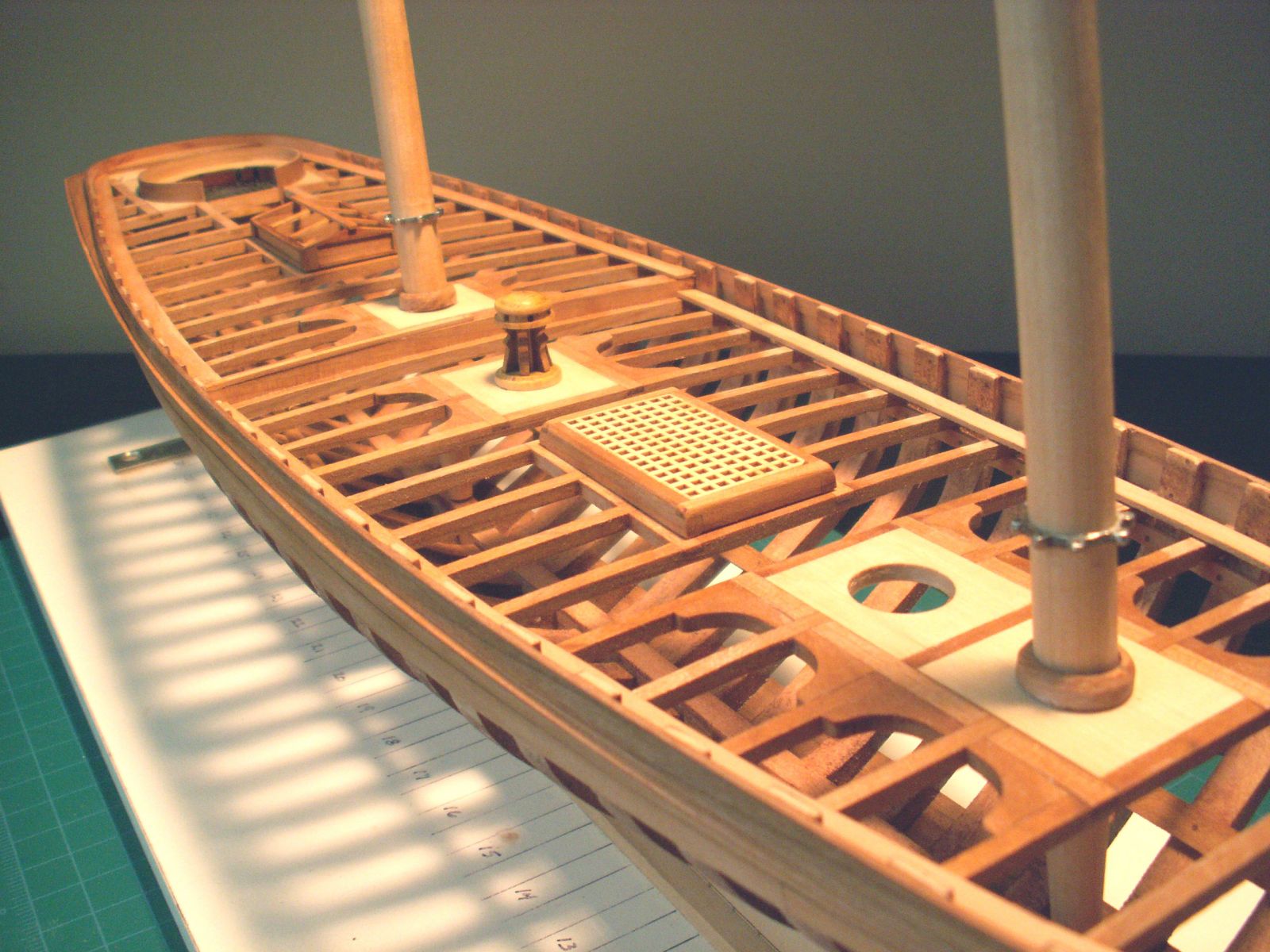
The two small hatches at the bow have these covers as does the large hatch in the middle of the deck. Your Top View plans will show this and you can see these completed hatches in the 6th photo.
In the 9th through the 14th photo you see how I constructed the hatch with the small house like structure in it. This is called a deck house. Photos 10 through 14 show the assembly of the deck house.
The final object to make is the windlass. The windlass was used to raise the anchor. It is an octagonal timber that tapered slightly at each end. It has several square holes in it so that long leverage poles could be inserted and used to turn the windlass.
The anchor rope was wrapped around the windlass so that when it was turned, it would raise the anchor. To make the windlass, start with a square piece of wood that is. You can obtain the length needed from the Top View plans. This piece must be trimmed on each corner for the full length to turn it into an octagonal piece as shown in the 16th and 17th photos.
After first shaping it with an Xacto knife, it is then reduced on all eight sides at each end so as to make it slightly tapered as shown in the 19th photo. In the 20th and 21st photo, I've marked two lines at one end. The lines are spaced. The outer line is. A rabbet joint is cut between these two lines using a 11 Xacto. This forms a recessed cylinder shape at each end as shown in the 21st photo. These cylindrical areas are used to mount the windlass to the windlass mounts shown in the 22nd photo.
Another recessed cylindrical area. As you can see, it has teeth. These might be difficult to make so if you can't carve the teeth into the cylindrical area I wouldn't worry too much about it. I started by first cutting the cylinder into the wood. Then I used the tip of the 11 Xacto to score and carve each individual tooth. It takes time to do this but the end result looks fantastic. The plans also show square holes cut into the surface of the 8 sides of the windlass. Then the holes can be squared up with a 11 Xacto.
Use your plans to mark the location of these holes on the sides of the windlass. The mount as shown in the 22nd photo is made of two piece of wood. The first piece is rectangular in shape makde from. For contrast, you might want to use boxwood instead. Two timberheads are cut in the upper portion of the part as shown in the photo. A half circle notch is cut in the upper area that will fit around the cylindrical area at the end of the windlass. The drawing with the file name "Side View" shows the shape of both parts and can be used as a template to make these parts.
The second piece is. It too has a half circle to fit the cylindrical part of the windlass. The 23rd photo shows the completed windlass assembly. In the remaining photos you can see the mounting of these hatches and the windlass. Holly is the preferred wood of model ship builders because of its clear, white color. The decks of ships were honed with special stones that acted like sand paper. This honing was done routinely to keep slime from building up on the deck which became slippery. The constant honing and bleaching by the sone made the decks turn white in color, thus the reason for using holly for the deck planking.
The deck planking has blackened edges. I like to use an artist's charcoal to blacken the edges because it does not bleed like a felt tip marker might. This blackening creates the effect of caulking between the rows of planks. These rods were round and slightly tapered but square at the ends where they were inserted into square holes in the windlass. As you can see in the last three photos, the holes in the windlass were staggered - on every other surface of the windlass.
They were also on the outside edges. The photo also reveals that the toothed area in the center has beeen painted black. This area was actually made of metal on a real ship. Another strip of metal called the tongue was attached to the aft side of the mast. It worked in a fashion that prevented the windlass from spinning in the opposite direction when the anchor was raised. To lower the anchor, this locking mechanism could be disengaged. Since I'm not going to be adding masts to the model, that detail will be left out.
You will also notice that the deck planking at the bow has a rectangular hole in it. This hole will have a bowsprit bitt installed later on. There is also a round opening in front of the windlass where the mast would go. Earlier when you framed the deck, there were two beams and two carlings very close together that formed a small square opening which is where this mast hole is located.
The rectangular hole for the bowsprit bitt is just in front of the forward most deck beam. This completes the details on the main deck. Our model is just about finished now. If you wanted you could add additional deck planking and purchase cannons from Model Expo to be installed on the deck.
I chose not to do this because I wanted to show the framework of the deck and typically an Admiralty model such as this did not have cannons installed. The primary purpose for the Admiralty model was to show the Admiralty Board what the ship's framework would be like, so such details were left off and were often up to the individual captain of the ship to decide. Now we will turn our attention to the quarterdeck and its deck furniture.
The quarterdeck has two hatches with grating covers that are made in the same manner as the main deck hatches. The first 3 photos show these hatches. There is also a large hatch in the center as shown in the photos. At the fore end of the deck is a structure called the bitts.
This structure consists of two tall posts with a cross beam that has a special shape. The 4th, 5th and 6th photo shows how the upper cross beam is made using a piece of. The posts can be made from the same stripwood but should be cut down to. The lower cross piece is also. You can use the Miscellaneous Parts drawing to obtain measurements of these pieces. The arched shaped upper cross beam is shaped by hand using a 22 Xacto. A bell hangs from the underside which can be purchased from Model Expo also.
As seen in the photo, two square holes are cut in the second plank on each side from the outside edge of the deck planking between the first beam and first ledge. You can start by drilling a small hole using a pin vise and a small drill bit. Then the hole can be enlarged using a 11 Xacto knife. The posts to the bitts fits int the hole being glued to the aft side of the deck beam.
The lower cross timber has notches cut into it on each end so that it can be fitted to the two posts as seen in the photo. The posts also have corresponding notches for the cross timber to mate to. The posts also have a small hole drilled through them at their base. This hole is a simulation of a sheave that would have been installed in the posts for certain rigging lines to pass through, but making and installing such a small detail is extremely difficult.
Behind the bitts is the mast hole which needs to be cut out from the planking. Drill a small hole to begin with and then enlarge it with a 11 Xacto. Now to finish off that middle hatch which is called a companionway.
Your Miscellaneous Parts plans will show the size of each side. These parts are assembled as shown in the 9th photo and are fitted inside the hatch coaming in the middle of the deck. Notice that the top is slightly slanted aft which is also shown on your plans.
The companionway has some thin. These give the companionway some contrast. Small hinges on the simulated doors are made by cutting small strips of black construction paper and gluing them with white glue.
A top was made from a piece of. The top is scored with a 11 Xacto to simulate two separate pieces and simulated hinges are made from black construction paper. The 10th and 11th photo shows the completed companionway. The next detail to make is the galley chimney.
Ships had an oven on the lower deck. Although no below deck details were made for this model, you can still show this chimney on the quarterdeck. It is made from a solid piece of wood measuring. Around the bottom, a small hatch coaming like structure is made using. First 2 sides are added around the chimney.
Then the other two sides are added. Once these four sides have been added, they are beveled slightly along the upper area. A top for the chimney is made from. The upper portion above the coaming is painted black. The chimney is glued into the square opening on the right side of the deck next to the companionway as seen in the 16th and 17th photo. Ships had pumps that were used to pump water out of the bottom of the ship that might accumulate from rough seas, leaks or rain.
These were called elm tree pumps because they were usually made from elm trees due to the tree's hardness and longevity when exposed to water. The 15th through the 18th photos show how these pumps are made. First cut the piece to length.
After tapering, bevel each corner from top to bottom to form an octagonal shape as seen in the 19th photo. Drill a small hole in the top surface the wide end and then bevel it slightly as shown in the photos. Finally, cut a notch in the top edge of the beveled end and add a tapered strip of. Paint the handle black as seen in the photo. The eighteenth photo shows these installed on the flat wood surface of the pieces added earlier when the deck was framed.
Orient the handles on an angle on the forward side as shown in the photos. The last detail tol make in this step will be the binnacle. The binnacle was a box like structure that housed a compass and a small candle or lantern inside.
It was used to aid in knowing the direction the ship was headed in. A man would work the tiller which was attached to the rudder to steer the ship on a certain compass heading. The binnacle is made in a similar fashion to the companionway using. Use your Miscellaneous Parts plan to get the length and width of each piece. Construction is shown in the 19yh through the 20th photos. Notice how the bottom edge is cut at an angle.
This is because the deck rises fore and aft. The angled bottom makes the binnacle stand straight when mounted to the deck. Trim the edges with swiss pear as shown in the photos. Mount the binnacle behind the companionway as shown in the 21st photo and top it off with a roof made from. The last photo shows the completed quarterdeck with all of its deck details.
In the next and final step, all remaining details will be made and added to the ship thus completing your construction of a true plank on frame model ship made from scratch.
Happy modeling! We're closing on on the finished model now! This is the last step in this Instructable. You will finish up the final details on the model in this step.
The first part to be made will be the channels with chainplates. These structures were part of the ship's rigging. Heavy lines came down from the upper area of the masts to the channels.
Special blocks called deadeyes were seized to the end of these heavy ropes. Corresponding deadeyes were attached to the channels using metal strops. These stropped deadeyes were then attached to the side of the ship using chainplates.
The two deadeyes were lashed together using the three holes in the deadeyes. This will make more sense to you when you view the photos. Brass wire purchased at a craft store I believe 24 or 22 gauge was used to make the strop. After the wire has been bent around the deadeye, a small loop is formed at the bottom, again being formed and bent using jeweler's needle nose pliers also found at most craft stores.
The excess wire is cut off and the strop is soldered in the middle leaving the small loop at the bottom open and exposed. Small jeweler's files are used to file away the excess solder. Finally, the deadeye and strop are painted black.
Photos two through five show these steps. The chainplates are made from flat brass or copper strips. Photo six shows some flat copper wire purchased from Model Expo. A small hole is drilled in one end and the other end is bent over at an angle. Small jeweler's files were used to taper the bent end so that it would fit into the hole in the strop.
The end where the hole was drilled was rounded on the corners with a jeweler's file and small notches were filed on each side to make this part of the chainplate look more separated. That end was also bent slightly at an angle opposite to the upper end. Finally these were painted black.
Photos 5 through 7 show the chainplates and some flat copper wire but brass wire may also be used, so long as it's flat otherwise you won't be able to drill the hole in the bottom end. Now to attach everything to the ship.
Your plans show the shape and location. The outside edges have small notches cut into them. A deadeye strop fits into each notch as shown in the 8th and 9th photos. A small strip of.
Then the chainplate is hooked onto the strop eye. A small brass nail is used to secure the bottom end to the wale plank. These nails can be purchased from Model Expo as well. Drill a small hole into the wale first, and then insert the nail into the hole using needle nose pliers.
The Model Ship Building Australia Quotes fit should be snug, and a touch of super glue can be used to secure the nail into the hole. There are two channels on each side of the ship, one for each mast. Your Top View and Side View plans show their location and dimension. At the front of the ship is a special post called the bowsprit bitt.
It is a rectangular post that is beveled at the top on all four sides. A square mortise is cut into the upper end. This mortise was used so that the bowsprit tenon could be mated to secure the bowsprit in place. A bowsprit is a special kind of mast that sat on the stem and protruded out from the front of the ship. First make the bowsprit bitt. Then cut the rectangular opening in the deck where it is inserted see the photo which shows it located just in front of the two forward hatches.
Temporarily install the bitt into the hole you just cut. Then lay a strip of scrap wood across the stem and mark where it intersects the bitt. Remove the bit, drill a starter hole through the bitt at the mark you made, then use a 11 Xacto to shape the hole into a square mortise. Finally, glue the bitt back into the hole. In the 10th and 11th photo you can see the timberheads have been shaped. You will recall that when you added the cap rails, these were left sticking above the rail.


|
Msc Boat Trips 2020 Time Ncert Solution Of Class 10th Hindi Kshitij Group Boat Questions Reddit Wifi Inexpensive Power Boats Tutorial |
